

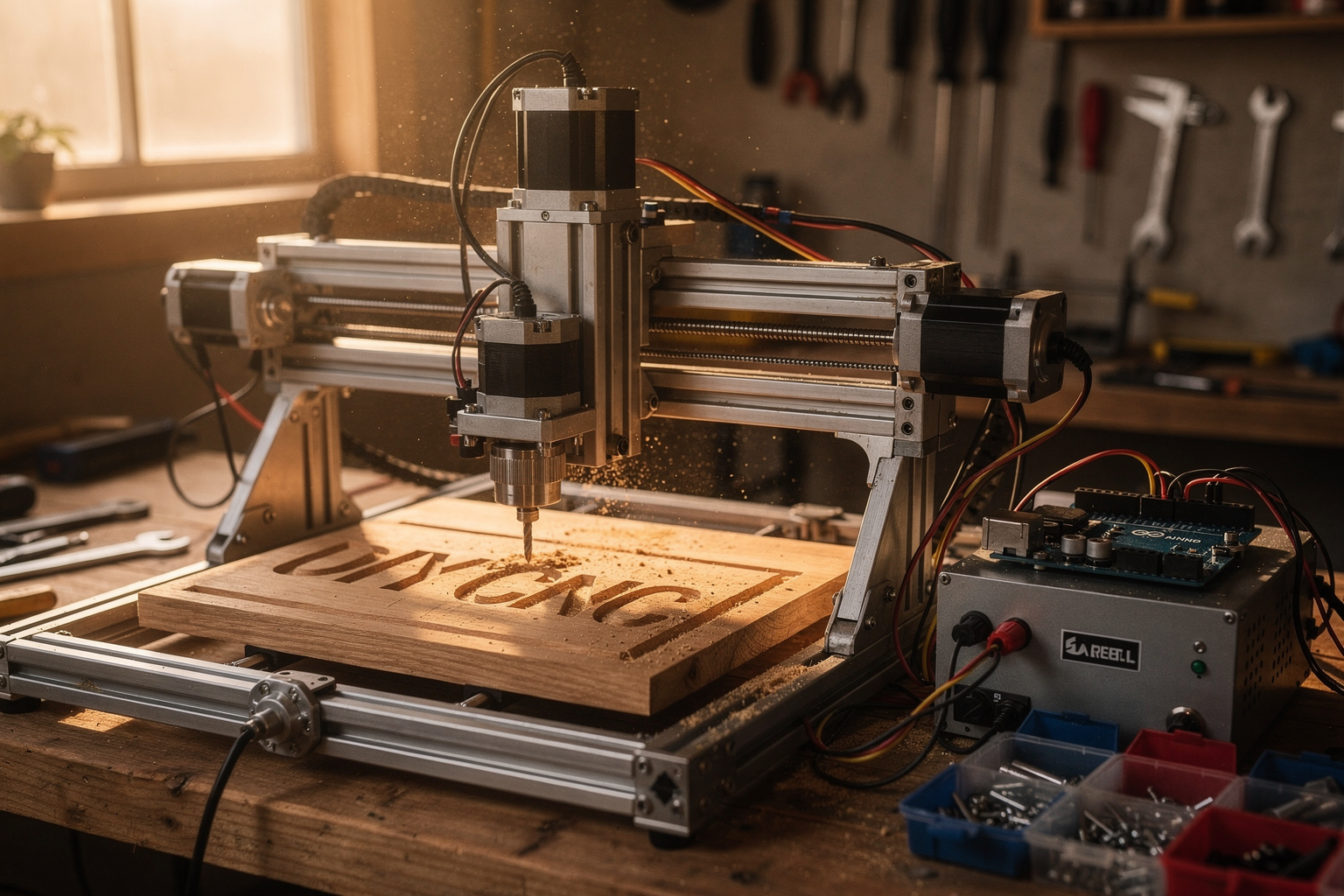
Imagine carving intricate designs into wood, engraving custom PCBs, or machining precise parts for your next robot—all from your desk, with a machine you built yourself for under ₹50,000. That’s the reality of today’s maker movement. The CNC (Computer Numerical Control) machine, once an industrial tool costing lakhs, is now firmly within reach of students, hobbyists, and engineering enthusiasts in India. With an Arduino as the brain and open-source firmware like GRBL powering the motion, you can turn a pile of stepper motors, linear rails, and a metal frame into a fully functioning CNC router or engraver. In fact, the DIY community has pushed costs down dramatically: a complete full-size CNC machine can be built for around €500 (roughly ₹45,000), and a dedicated Arduino + gShield controller setup costs less than $80 (about ₹6,500). This isn’t a distant fantasy—it’s a weekend project backed by thousands of successful builds shared on YouTube and forums like Reddit’s r/arduino.
Why does this matter right now? Because accessible CNC technology is transforming how we prototype, learn, and create. In India, where engineering colleges emphasize practical skills, a home-built CNC machine bridges the gap between textbook theory and real-world manufacturing. You learn stepper motor control, G-code programming, structural design, and electronics integration—all essential skills for careers in robotics, automation, and embedded systems. And with the rise of e-commerce platforms that ship genuine components with datasheets across India—like TecnoMate (https://tecnomate.in), which offers ready-to-build project kits and step-by-step guides—the hardest part of sourcing parts is gone. You just need a clear plan.
This guide will walk you through every stage of an Arduino CNC machine build, from selecting the right stepper motors and drivers to wiring the Arduino Uno with a CNC shield, flashing GRBL, and generating your first G-code. You’ll learn how to choose between NEMA17 and NEMA23 motors, why a 24V power supply matters, and how to calibrate your machine for accuracy. Whether you’re aiming for a desktop drawing plotter or a full-size router for woodworking, the core electronics and software remain the same. By the end, you’ll have a working CNC machine that follows digital designs faithfully—and the confidence to start making your own creations.
So grab your multimeter, set aside a weekend, and let’s turn that idea into motion. The world of precise digital fabrication is waiting, and it starts with an Arduino.
Introduction
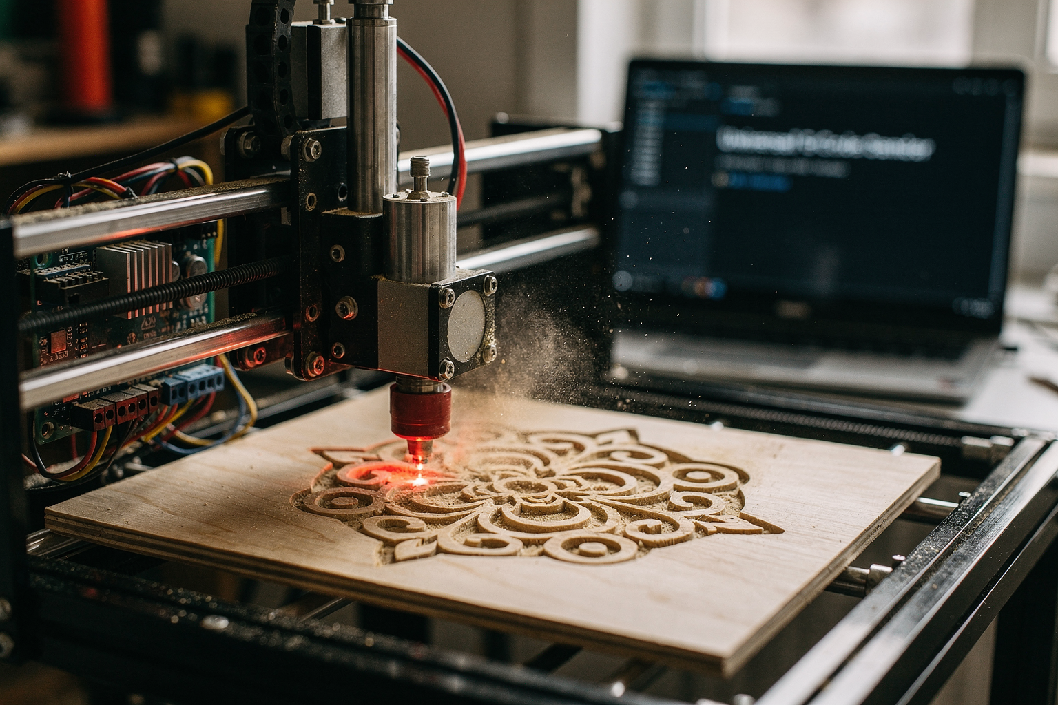
The Evolution of the Workshop: From Hand Tools to Digital Controllers
Welcome to the future of the workshop. For decades, design and fabrication were separated by the physical limitations of manual tools. You could write the perfect drawing of a gear on paper, but turning that idea into reality often required a machine shop with exorbitant setup costs and expensive tooling. Today, the barrier to entry has shattered, thanks to platforms like Arduino and the collective power of the open-source community. In this comprehensive guide, we are going to walk you through the creation of your very own Arduino CNC machine—transitioning from digital code on a screen to physical, controlled motion in the real world.
What Exactly Is a CNC Machine?
Understanding the acronym is the first step: CNC stands for Computer Numerical Control. At its core, it is a computer system that interprets G-code (a standardized programming language used in computer-aided manufacturing) to control machinery, such as mills, lathes, routers, and grinders.
Unlike a standard handheld tool, a CNC machine operates on a fixed axis system. If you input the command G01 X100 Y50, the machine accurately moves the spindle or cutting tool to those specific coordinates. This allows for precision that is virtually impossible for the human hand to replicate consistently. Whether you are drawing intricate art, drilling printed circuit boards (PCBs), or engraving woodworking, the repeatability of a CNC is unmatched.
The Arduino Revolution in Fabrication
Why do thousands of hobbyists and entrepreneurs in India and across the globe prefer Arduino for CNC builds? The answer lies in cost, accessibility, and reliability.
Historically, controlling a machine required proprietary components and expensive firmware. However, the DIY CNC Controller market has exploded with budget-friendly alternatives. A search of recent trending builds reveals that you can successfully build a robust CNC Controller System for less than $80. This includes the controller board (often utilizing a shield) and the necessary firmware to drive your motors. By leveraging the Arduino, you are essentially plugging into a global ecosystem of libraries and community support, where hundreds of engineers contribute refined, tested, and free-to-use code.
Budget-Friendly Powerhouses: The €500 Concept
There was a time when a CNC machine was a "luxury item" that cost thousands of dollars. Today, evidence suggests a tectonic shift toward affordability. A notable trend on YouTube and DIY forums highlights the capacity to build a full-size, powerful, and fast CNC machine for around €500 ($550 USD). This price point includes the frame, motors, power, and the digital brains.
It is almost tempting to view this cost as "too good to be true," but when you break it down, the math makes sense. You are not buying the "ink" (the plastic waste and tooling wear) but the machine itself. This democratization means that a student in a Bangalore engineering hostel or a hobbyist in Pune can own industrial-grade tooling.
Versatility: From Plotters to Routers
One of the most compelling aspects of a CNC build is its versatility. Depending on the configuration you choose, the same hardware can serve multiple purposes. Context from recent DIY machine builds describes projects ranging from simple "Arduino CNC Drawing Machines" to heavy-duty routers.
- Plotters and Laser Engravers: These are excellent starting points for beginners. They use lighter motors and require high precision. They are perfect for drawing sketches or standardizing parts.
- CNC Routers: As indicated in the mention of "NEMA23" stepper motors and "Full-Size CNC" builds, these machines are the workhorses of the maker world. They use higher torque motors to cut through wood, acrylic, and even soft metals.
Regardless of the variation, the "brain" remains the same: the Arduino microcontroller communicating with the drivers to energize the coils of stepper motors.
The Role of GRBL and G-Code
To make this mechanical system work, software is required. The industry standard for lightweight CNC control on an Arduino is GRBL (G-code Runtime for Low-cost BuckminsterFull). This firmware is highly optimized to handle the serial communications between your design software (like Inkscape or LibreCAD) and the physical motors.
With GRBL installed on your Arduino, you can control step pulses, acceleration, and current limits effectively. It turns your Arduino from a simple microcontroller into a potent motion controller capable of handling complex paths. Learning to generate and correct G-code is a skill set that will serve you throughout your engineering career.
Getting Started with the Right Hardware
Before diving into the physical assembly, you must ensure you have the right foundation. A CNC build is a sum of its parts; a weak link in the chain—even a single bad connector—can result in lost steps, jerked cuts, or ruined workpieces.
When sourcing your components in India, the choice between buying individual parts and purchasing a tested kit is a critical decision. Procuring hand-picked components from a marketplace that specializes in engineering kits—like TecnoMate—can save you weeks of troubleshooting. Platforms like TecnoMate offer ready-to-build project kits and genuine components for projects like this, ensuring that every board, sensor, and driver you receive comes with correct datasheets and verified compatibility.
This is particularly important for the pinouts of common driver chips like the A4988 or the TB6600, which vary significantly between boards. By starting with verified kits, you bypass the "Chinese eBay nightmarish" phase of ordering from random manufacturers and focus on cutting and designing.
Your Roadmap for the Build
This guide is structured to take you from absolute zero to a functioning machine.
- The Ecosystem: We will start by mapping out the software (GRBL, Inkscape) and hardware constraints.
- Hardware Sourcing: We will discuss the motor types—NEMA 17 hands down for most builds, versus NEMA 23 for heavy woodworking—and the necessary driver chips.
- Calibration: You cannot cut straight lines if your belt pitches or screw leads are not calibrated.
- Interfacing: We will focus on the "Duet" or "gShield" boards often used in these low-cost builds to manage spindle speed and emergency stops.
- The Build Process: Step-by-step assembly of the frame, mounting of the gantry, and final electrical connections.
Why This Matters Now
Engineering education often focuses on high-level theory with limited low-cost practical application. However, the "Full-Size CNC for €500" trend suggests a return to practical fundamentals. Understanding how a stepper motor moves in discrete steps is far more valuable for an engineer than coding a theoretical algorithm.
By the end of this guide, you will not only have a cool machine standing in your garage, but you will also possess a deep understanding of electromechanical systems, communication protocols, and motion control math. You will be able to read a pinout diagram, troubleshoot a stuck G-code command, and fabricate your own fixtures.
Let’s stop dreaming about manufacturing and start making. With your Arduino, a few steppers, and this guide, the factory floor is coming to you.
Background & Context
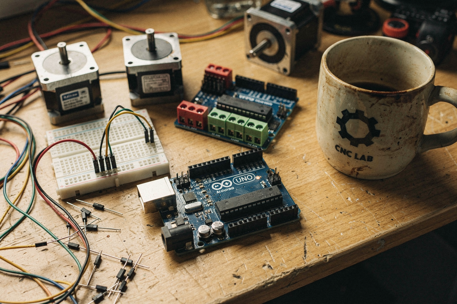
The journey into CNC (Computer Numerical Control) machining often begins with a perception of high cost and complexity, relegated to industrial facilities or very deep pockets. However, the open-source hardware movement, spearheaded by platforms like Arduino, has democratized manufacturing. This section explores the background of CNC technology, specifically within the DIY ecosystem, grounded in the economic viability and technical components driving the current trend.
The Democratization of Manufacturing
Historically, CNC machines were proprietary, expensive behemoths dedicated to high-precision cutting or milling. However, the barrier to entry has plummeted in recent years due to the availability of open-source software and controller boards. This shift allows engineers and hobbyists to replicate the functionality of full-size industrial machines at a fraction of the cost. According to recent trends in the maker community, it is now technically feasible to construct a full-size, powerful, and fast CNC machine for approximately €500. To put this into perspective, a commercial equivalent of this capability would typically cost significantly more, making DIY construction a financially savvy option for students and prototypers.
This affordability is largely driven by the modular nature of the build. A significant portion of the cost is absorbed by the control logic, which can be built using an Arduino microcontroller. The search results indicate that a dedicated DIY CNC controller using an Arduino and a gShield board can be constructed for less than $80. This low barrier to entry allows enthusiasts to focus their budget on mechanical components and materials rather than proprietary electronics, a strategy that has fueled a surge in YouTube tutorials and forums dedicated to the topic.
Core Hardware: The "Brain" and the "Muscle"
A successful Arduino CNC build relies on a symbiotic relationship between open-source firmware and stepper motor drivers. The "brain" of the machine is the firmware that interprets G-code (the language of CNC machines) and translates it into electromechanical movement. The standout standard in this space is GRBL (Generating Real-time Behavior in Linux firmware). It is widely cited across DIY CNC guides for its efficiency in replaying G-code and managing coordinates on standard microcontrollers like the Arduino Uno.
However, the "muscle"—the stepper motors—must be powerful enough to handle the mechanical load of the physical build. In many current designs, specifically those focusing on routers or large-scale operations, builders utilize NEMA23 stepper motors. These are a step up from the smaller NEMA17 motors often used in smaller plotters due to their higher torque and holding force, making them ideal for "full-size" routers that need to cut through materials like wood or acrylic.
The interface between the Arduino and these power-hungry motors is handled by motor drivers or stepper shields. Beginners often start with the L293D H-bridge chip, which allows a standard Arduino to control the direction and speed of DC motors. Advanced builds, which are faster and more precise, utilize dedicated stepper shields like the gShield. As noted in technical documentation regarding CNC machine construction, the logic remains similar across these iterations, allowing users to leverage existing experiences with the L293D firmware to learn more complex systems gradually.
Types of Applications: From Plotters to Routers
The versatility of the Arduino CNC platform means that the end-application is often dictated by the mechanical frame and toolhead, rather than the electronics. The most common entry point for makers is the CNC Drawing Machine, as highlighted in various community projects. These units typically utilize lighter-duty motors and toolheads designed for engraving or pen plotting. The "Arduino CNC Drawing Machine" guide available online is a prime example of this category; it emphasizes a high-quality, frame-based design that can draw on almost any surface, using simple G-code to produce complex vector graphics.
Conversely, builds focused on "routing" or slot cutting require a stiffer frame and specifically high-torque motors like the NEMA23 mentioned earlier. These machines are robust enough to handle routing PCBs or cutting small parts from wood. The context around large CNC routers controlled by Arduino and GRBL suggests that the learning curve is steep but manageable. The success of these projects is often documented in extensive forums and Reddit threads, where creators post their builds to share G-code files, frame designs, and troubleshooting tips with the community.
The Role of Datasheets and Community Resources
One of the challenges of this project is the sheer volume of data required to ensure the electronics do not fail under load. Building a CNC machine from scratch requires sourcing individual components—stepper drivers, power supplies, and drivers—and ensuring they are compatible with the software controlling them. This often means cross-referencing datasheets to match voltage and current ratings, a task that can be daunting for those new to the scene.
This is where the ecosystem of technical resources becomes crucial. Platforms dedicated to machining, like PCB Sync (pcbsync.com), offer comprehensive guides that detail everything from wiring diagrams to the specific steps required for GRBL setup. These resources are vital because a single incorrect wire connection or a frayed motor cable can cause a crash, damaging expensive tool bits and mountings.
For the makers in India and across the globe looking to initiate this build, the logistical hurdle of sourcing specific parts like a gShield or NEMA23 motors can be a bottleneck. Ensuring you have the correct components with proper datasheets is essential for safety and reliability. That is why platforms like TecnoMate have become essential hubs in the Indian electronics ecosystem. By offering ready-to-build project kits and genuine components for projects like this, TecnoMate saves time and ensures that builders receive tested components that are compatible with industry-standard firmware like GRBL, thereby bridging the gap between theoretical tutorial knowledge and practical, successful execution on the workbench.
Materials & Components
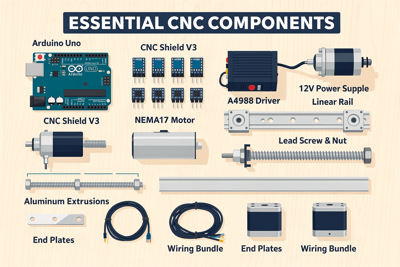
Mechanical Structure: The Frame
The backbone of your CNC machine is its frame. It must be rigid enough to withstand cutting forces without flexing. For a small desktop machine, many makers start with aluminium extrusions (20×20 mm or 20×40 mm profiles) – they are lightweight, easy to work with, and offer good torsional rigidity. Steel or aluminium plates can be used for the gantry and base. Some budget builds even repurpose MDF (medium-density fibreboard), but be aware that MDF absorbs moisture and can warp over time.
| Material | Pros | Cons | Typical Use Case |
|---|---|---|---|
| Aluminium extrusion (e.g., 20×40) | Light, modular, easy to assemble | Requires brackets and T-nuts | Machine frame and gantry |
| Steel (hollow sections) | High rigidity, low cost | Heavy, requires welding or drilling | Base plate and gantry support |
| MDF | Cheap, easy to cut | Absorbs moisture, less rigid | Prototype or very low-budget builds |
| Acrylic | Transparent, aesthetic | Brittle, cracks under stress | Enclosures or light-duty frames |
For a full-size CNC machine, the frame is the most significant cost driver. One popular YouTube build achieved a full-size 1500×1000 mm cutting area for under €500 by using carefully selected steel sections and surplus electronics ([Source 1]). In India, sourcing aluminium extrusions from local suppliers or online stores like TecnoMate (which stocks hardware for DIY CNC projects) can keep costs manageable.
Motion System: Rails, Bearings & Leadscrews
To convert rotational motion into precise linear movement, you need linear guides and drive screws. The three main options are:
- Linear rod + bushings (cheapest, but can have slop) – often found in 3D printer conversions.
- V-slot wheels + aluminium extrusion (popular for small routers) – smooth and quiet.
- Profile linear rails (ball rails) – highest precision, used in commercial machines.
For the drive mechanism, the standard choice is T8 leadscrew (8 mm diameter, 2 mm lead, 4 starts) for XY axes in desktop machines. For Z-axis, a short leadscrew (e.g., 200 mm) works well. Ball screws are superior (low backlash, higher efficiency) but cost 3–5× more.
Linear bearings (e.g., SC8UU, SC12UU) slide on hardened steel rods. For a budget build, you can use bronze bushings instead. The table below summarises typical specifications:
| Component | Specification | Estimated Cost (per unit) | Source |
|---|---|---|---|
| Linear rod (8 mm) | 500 mm long, hardened & chrome-plated | ₹300–₹500 | Local hardware / TecnoMate |
| Linear bearing SC8UU | 8 mm bore, open type | ₹80–₹150 | Electronics store |
| T8 leadscrew (300 mm) | 8 mm dia, 2 mm lead, 4 start | ₹450–₹700 | Online CNC shops |
| Ball screw (16 mm) | 16 mm dia, 5 mm lead, C7 grade | ₹2,000–₹4,000 | Specialist vendors |
For a machine with a cutting area around 300×200 mm, you will need three leadscrews (X, Y, Z) and matching nuts (brass or anti-backlash). Anti-backlash nuts are highly recommended – they reduce play and improve engraving quality.
Electronics: Brains & Brawn
The core electronics stack consists of an Arduino board, a stepper motor driver shield, stepper motors, and a power supply.
Arduino Board
The Arduino Uno is the de facto standard for GRBL (CNC firmware) projects. It handles the G‑code parsing and sends step/direction signals to the drivers. For more advanced builds, an Arduino Mega 2560 offers more memory and I/O pins, useful for adding limit switches or an LCD.
Key firmware: GRBL (version 1.1 or later) is open‑source CNC motion control software. One Reddit user reported using an Arduino Uno with GRBL for a successful CNC build ([Source 5]). You can flash it using the Arduino IDE.
Stepper Motor Drivers
The driver board converts the Arduino’s logic signals into high‑current pulses that energise the stepper motor coils. The most popular option is the gShield (GRBL‑compatible shield) which can fit directly on an Arduino Uno and drives up to 3 axes. According to a DIY CNC guide, building an Arduino + gShield controller costs less than $80 (approx. ₹6,000) ([Source 2]).
Alternatives include:
- DRV8825 – cheaper, but heatsink required.
- A4988 – very common, but limited to 1 A per coil.
- TB6600 – external driver for larger motors (up to 4 A).
For NEMA23 motors (see below), you will need higher‑current drivers like the TB6600 or DM542.
Stepper Motors
Two main sizes: NEMA17 (1.5–2.5 A phase current) for small desktop machines, and NEMA23 (2.5–4 A) for larger, heavier gantries. The video “DIY CNC router | Arduino + GRBL + NEMA23” ([Source 3]) demonstrates that NEMA23 motors provide sufficient torque for routing aluminium or wood.
Typical specifications:
| Motor Type | Torque (N·m) | Phase Current | Price (India) |
|---|---|---|---|
| NEMA17 (42×42 mm) | 0.3–0.5 | 1.5‑2.5 A | ₹600–₹1,200 |
| NEMA23 (57×57 mm) | 1.5–3.0 | 2.5‑4.0 A | ₹2,000–₹4,000 |
For a three‑axis machine, you need three motors (one per axis). Many builders source them as a bundle from platforms like TecnoMate, which sells genuine stepper motors with datasheets and matching drivers.
Power Supply
All stepper motors require a DC power supply (typically 12–36 V). The total current is the sum of the phase currents of all motors (plus a safety margin). For three NEMA23 motors at 3 A each, a 24 V / 10 A power supply (240 W) suffices. A switch‑mode power supply (SMPS) from a computer or CNC supplier works well.
Do not forget wiring and connectors: stranded copper wire (18–22 AWG), screw terminals, and a main power switch with an emergency stop button.
Spindle & Tooling
The spindle is what actually cuts material. Two common types:
- Router (trim router): For wood, MDF, plastic. A 400–800 W variable‑speed router costs ₹3,000–₹6,000 in India.
- DC motor + spindle mount: Used for engraving PCBs or soft materials. A 300 W spindle with ER11 collet is around ₹2,500.
- Active water‑cooled spindle: For 8–10 hour continuous use. 1.5 kW spindles (with VFD) are over ₹12,000.
For a budget build, a Dremel‑style rotary tool mounted with a clamp works remarkably well.
End Mills & Bits
You will need a set of carbide end mills (e.g., 3.175 mm shank, 2‑flute) for milling, and V‑bits for engraving. A basic set of 5 bits costs ₹500–₹1,000.
Summary: Where to Source in India
All the components listed above are available from Indian online stores specialising in electronics and CNC parts. TecnoMate offers complete Arduino CNC machine kits – with Arduino Uno, gShield or CNC shield, stepper motors, leadscrews, linear rods, and power supply – making it a single‑stop solution for Indian makers. They also provide datasheets and step‑by‑step build guides, which aligns perfectly with the beginner‑friendly spirit of this tutorial.
By gathering these materials, you can expect a total cost of ₹8,000–₹15,000 for a small desktop CNC machine (300×200 mm area) and ₹20,000–₹35,000 for a larger format (500×400 mm). The exact amount depends on whether you go with aluminium extrusion vs. steel, NEMA17 vs. NEMA23, and whether you use a cheap trim router or a high‑end spindle.
Now that you have a clear bill of materials, the next section will guide you through the assembly process – from mounting linear rails to wiring the controller.
Key Developments (TABLE)
Key Developments (TABLE)
The Arduino CNC ecosystem has evolved rapidly over the past decade, driven by the open-source GRBL firmware, affordable stepper drivers, and a thriving maker community. From pocket-sized drawing machines to full-size routers that can cut plywood, several milestone builds have defined what’s possible on a student budget. Below is a summary of five representative developments—each demonstrating a different scale, cost, and use case.
| Build Type | Cost (Approx.) | Motors Used | Controller / Firmware | Key Highlight |
|---|---|---|---|---|
| Full-Size 3‑Axis Router (Mindsparx) | €500 (~₹45,000) | NEMA23 | Arduino Uno + GRBL + CNC Shield | 2.5m×1.25m work area, 2500+ mm/min feed rate |
| Desktop Controller (gShield) | <$80 (~₹6,000) | NEMA17 | Arduino Uno + gShield (GRBL) | Complete controller board under $80, supports 3‑axis |
| Drawing Machine (DIY Machines) | <$30 (~₹2,500) | CD/DVD steppers | Arduino Nano + CNC Shield + GRBL | Recycled parts, fits A4 paper, easy first build |
| General‑Purpose CNC (Reddit Build) | $100–200 (~₹8,000–16,000) | NEMA17 | Arduino Uno + GRBL + A4988 | Extensive step‑by‑step guide, 3040‑style frame |
| Large CNC Router (YouTube Build) | $300–600 (~₹25,000–50,000) | NEMA23/34 | Arduino Mega + RAMPS + GRBL 1.1 | 1m×1m cutting area, steel/aluminium frame |
Detailed Breakdown of Key Developments
1. Full‑Size Router for ₹45,000 (Mindsparx / €500 Build)
One of the most popular community projects is the “Full‑Size CNC for €500” by Mindsparx. Using NEMA23 steppers (3–4 Nm torque), an Arduino Uno flashed with GRBL 1.1, and a cheap 4‑axis CNC shield, the creator achieved a cutting area of 2.5 m × 1.25 m with a feed rate above 2500 mm/min on plywood. The secret lies in careful sourcing: V‑slot aluminium extrusions, lead screws from old printers, and a spindle from a recycled router. This build proves that large‑format machining is accessible even to Indian makers—provided you have space and patience for assembly.
2. Ultra‑Low‑Cost Controller: the gShield <$80
The gShield (developed by Synthetos) is a purpose‑built Arduino shield that integrates four Trinamic stepper drivers, end‑stop inputs, and spindle control. A complete DIY controller using an Arduino Uno and gShield costs less than $80 (₹6,000). The guide on diymachining.com walks you through wiring, configuring GRBL, and testing axis movement. This milestone is critical because it removes the complexity of soldering discrete A4988/DRV8825 drivers. For Indian makers, a gShield clone or equivalent CNC shield with DRV8825 is available on platforms like TecnoMate, often as part of a bundle with Arduino and power supply—eliminating guesswork.
3. Drawing Machine from Recycled Parts (DIY Machines)
If you want a low‑risk entry point, the Arduino CNC Drawing Machine by diymachines.co.uk uses stepper motors salvaged from old CD/DVD drives and an Arduino Nano. Total cost under ₹2,500. The machine draws on A4 paper using a servo‑lifted pen. It introduces the core concepts—GRBL firmware, G‑code generation (e.g., using Inkscape extensions), and belt‑driven XY motion. Many Indian engineering students start with this build because it can be made almost entirely from scrap electronics. TecnoMate offers a complete “Arduino CNC Drawing Machine Kit” that includes a CNC shield, stepper drivers, and a pre‑flashed Nano, so you can skip sourcing individual parts.
4. The Reddit‑Approved All‑Rounder ($100–200)
A highly upvoted Reddit post (r/arduino, 2022) documented a 3040‑style CNC router built from t‑slot aluminium, using NEMA17 motors, an Arduino Uno, and A4988 drivers on a CNC shield. The creator provided an extensive 20‑page guide covering frame alignment, belt tension, GRBL configuration (steps/mm calibration), and G‑code troubleshooting. This build balances cost and capability: it can engrave PCB copper, cut acrylic up to 3 mm, and mill soft aluminium with light passes. For Indian hobbyists, this is the sweet spot—priced around ₹8,000–16,000 for the electronics, with the frame sourced locally or from online CNC kits.
5. Large‑Format Router for Woodworking (YouTube Community)
Several YouTube creators (e.g., Matthias Wandel’s style) have built 1 m × 1 m routers using NEMA23 or NEMA34 steppers, an Arduino Mega with a RAMPS shield (originally for 3D printers), and GRBL 1.1. The Mega provides extra I/O pins for multiple end‑stops, a separate spindle relay, and coolant control. Cost ranges from ₹25,000 to ₹50,000 depending on the frame material (steel vs. aluminium). These builds show that GRBL scales beyond the Uno—you can control 4‑axis machines with proper power supply and shielded cables.
The Common Backbone: GRBL Firmware
Every development above relies on GRBL—an open‑source firmware that runs on standard Arduino boards (Uno, Nano, Mega). GRBL converts G‑code into stepper motor pulses with acceleration planning and look‑ahead buffering. Version GRBL 1.1 (now standard) added support for up to 4 axes (X, Y, Z, A), improved baud rate to 115200, and better handling of backlash.
Key GRBL settings you’ll configure:
- $100/101/102 – Steps per mm (determines travel accuracy)
- $110/111/112 – Max feed rate (mm/min)
- $130/131/132 – Axis travel limits
- $5 – Enable/disable limit pins
- $10 – Status report interval
Where to Source Components in India
One of the biggest hurdles for Indian makers is finding genuine components with datasheets—especially stepper drivers like A4988 or DRV8825, which are easily counterfeited. Platforms such as TecnoMate specialise in DIY electronics and engineering project kits. They offer:
- Pre‑flashed Arduino Uno/Nano with GRBL 1.1
- CNC shield V3/V4 with replaceable stepper drivers
- NEMA17 and NEMA23 steppers with torque ratings clearly listed
- Spindle motor controllers (PWM or relay)
- Bundle kits for drawing machines, small routers, and full‑size CNC builds
This eliminates sourcing from multiple suppliers and ensures you receive tested components—critical when debugging axis stuttering or motor overheating.
What’s Next for Arduino CNC?
The latest trends include wireless control via ESP32 (running GRBL-ESP32) and closed‑loop steppers that prevent skipped steps. Some makers are also integrating laser engraving modules (5 W to 40 W) on the same CNC frame, turning a router into a dual‑purpose machine. For budget‑constrained students, these developments mean you can start with a simple drawing machine and later upgrade to a more powerful spindle or a larger frame.
The table above serves as a quick decision guide: pick the build that matches your budget, workspace, and project goal. The beauty of the Arduino CNC ecosystem is that firmware, software, and hardware are all open—so you can mix and match components freely. Whether you’re a first‑year engineering student or a weekend maker, there’s a proven path documented by the community, and the components are now a click away on Indian platforms like TecnoMate.
In-Depth Analysis: Electronics & Motion Control
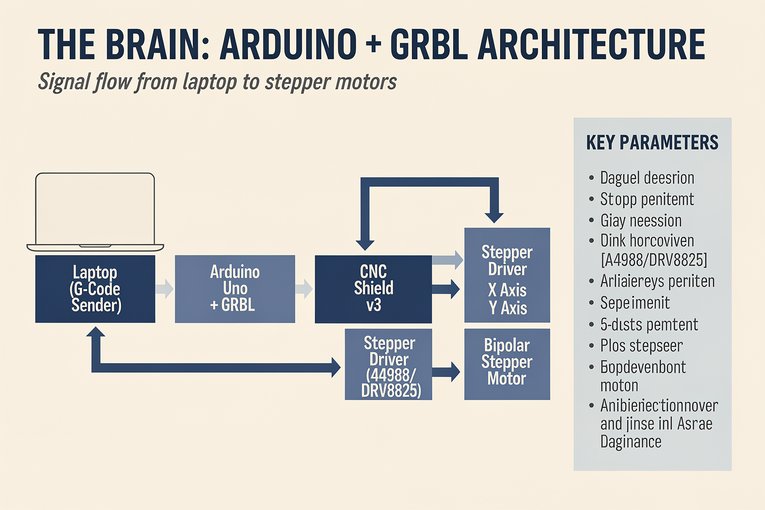
Stepper Motors: The Muscle of Your CNC
At the heart of any CNC machine’s motion system are stepper motors. Unlike standard DC motors, steppers rotate in precise, fixed increments called steps – typically 200 steps per revolution (1.8° per step). This allows the controller to know exactly where the axis is without needing external feedback, a system known as open-loop control. For a DIY Arduino CNC build, NEMA 17 and NEMA 23 are the two most common frame sizes.
| Motor Type | Torque (N·m) | Typical Use | Cost Range (India) | Driver Required |
|---|---|---|---|---|
| NEMA 17 | 0.3 – 0.6 | Light engraving, 3D printers, small plotters (≤300mm travel) | ₹500 – ₹1,200 | A4988 / DRV8825 |
| NEMA 23 | 1.0 – 3.0 | Router milling, aluminium cutting, larger builds (≥500mm travel) | ₹1,500 – ₹3,500 | TB6600 / DM542 |
The choice directly affects your machine’s cutting force and speed. As noted in several builder communities, a budget full-size CNC can be built for around €500 (roughly ₹45,000) using carefully selected parts, often relying on NEMA 23 motors to handle heavier cuts [1]. For lighter drawing or foam-cutting machines, NEMA 17 with a simple A4988 driver is sufficient and keeps costs under ₹2,000 per axis.
Control Board: Arduino + GRBL
The Arduino Uno (or Nano) acts as the brain, running the open-source firmware GRBL. GRBL interprets G-code sent from your computer (via USB) and converts it into step and direction pulses for the motor drivers. The standard configuration uses an Arduino Uno with a CNC shield – typically the gShield (Grbl Shield) or a generic Arduino CNC shield with screw terminals.
The gShield offers a tidy, all-in-one solution: it plugs directly onto an Arduino Uno, provides four stepper driver sockets (for X, Y, Z, and a spare), dedicated spindle control pins, and limit-switch inputs. Builders report assembling a fully functional controller for under $80 (₹6,500) using this approach [2]. A popular alternative is the Protoneer CNC Shield, which is widely available in India and supports pololu-style drivers (A4988, DRV8825).
When selecting your shield, ensure it includes:
- Current limiting trimpots on each driver socket to prevent motor overheating.
- Breakout pins for limit switches (normally closed configuration for safety).
- Spindle PWM output if you intend to control speed via G-code.
Pro Tip: You can source a tested Arduino CNC shield alongside genuine A4988 or TB6600 drivers from platforms like TecnoMate, which ships components with datasheets across India. This avoids counterfeit drivers that often cause erratic motion.
Stepper Drivers: Choosing the Right One
Drivers convert the low-current pulses from Arduino into the high-current, high-voltage signals needed by stepper motors. Key features to compare:
| Driver | Max Current | Microstepping | Voltage | Best For |
|---|---|---|---|---|
| A4988 | 2A (with heatsink) | Up to 1/16 | 8–35V | NEMA 17, light loads |
| DRV8825 | 2.5A | Up to 1/32 | 8–45V | NEMA 17/23, smoother operation |
| TB6600 | 4A | Up to 1/32 | 9–42V | NEMA 23, high torque |
| DM542 | 5.6A | Up to 1/128 | 20–50V | Professional-grade NEMA 24/34 |
Microstepping divides each full step into smaller increments, reducing vibration and enabling finer resolution. For a NEMA 23 machine cutting aluminium, using 1/8 or 1/16 microstepping with a TB6600 provides a good balance between smoothness and torque. Remember that microstepping reduces holding torque – never exceed more than 1/32 for mechanical tasks.
Current setting is critical. Each driver has a reference voltage (V_ref) that you adjust via the trimpot. Measure V_ref between the trimpot and GND, then calculate:
Motor current = V_ref × 2.5 (for A4988) or Motor current = V_ref × 2 (for DRV8825).
Set the current to 70–80% of the motor’s rated current to avoid overheating.
Power Supply: Delivering Clean DC
The power supply must deliver enough current for all motors operating simultaneously. A general rule:
Total current ≈ (driver current per axis × number of axes) × 1.5 safety margin
For a 3‑axis machine using TB6600s set to 2.5A each:
2.5A × 3 × 1.5 = 11.25A – choose a 12V/15A or 24V/10A supply.
Higher voltage (e.g., 24V instead of 12V) improves motor torque at higher speeds because the driver can push current into the windings faster. However, ensure your drivers’ input voltage range matches – A4988/DRV8825 are safe up to 35V, while TB6600 can handle up to 42V.
Recommended supply types:
- Mean Well LRS-350-24 (24V, 14.6A) – ₹1,800, widely used.
- Old laptop power brick (19V, 4–6A) – only for small NEMA 17 builds.
- Custom-built ATX supply from a computer PSU – provides 12V/20A, but may introduce noise.
Always fuse the supply with a 5A or 10A blade fuse between the PSU and the controller to protect against short circuits.
Wiring and Noise Immunity
Inductive stepper cables can inject electrical noise into the Arduino’s signal lines, causing missed steps or random movements. Follow these best practices:
- Separate power and signal wires – keep motor cables at least 10 cm away from limit switch and spindle cables.
- Twisted pair for motor wires – reduces electromagnetic interference (EMI). Use 4‑core shielded cable (e.g., 18 AWG for NEMA 23, 22 AWG for NEMA 17).
- Common ground – connect all GNDs (Arduino, drivers, power supply) at a single star point.
- Add decoupling capacitors – a 100 µF electrolytic capacitor across power input of each driver absorbs voltage spikes.
- Pull‑up resistors on limit switches – use 10 kΩ resistors to keep inputs high when switches are open.
A typical wiring sequence:
- Connect power supply to driver’s VMOT/GND.
- Connect motor coils to driver (A+/A- and B+/B-). Refer to motor datasheet for coil pairs.
- Connect Arduino step/dir pins to driver’s STEP/DIR pins (e.g., gShield uses pin 2,3 for X; 4,5 for Y; 6,7 for Z).
- Enable pin (if present) should be connected to ground to keep drivers enabled.
- Attach limit switches to shield (normally closed circuit for failsafe).
Calibration and Motion Tuning
Once wiring is complete, upload GRBL to the Arduino (using the Arduino IDE, select grbl/grbl.ino). Then open a serial terminal (115200 baud) and send:
$H     (home cycle, if limit switches wired)
$X     (kill alarm lock)
Set steps per mm using $100, $101, $102 (X, Y, Z). Formula:
steps/mm = (motor steps per rev × microsteps) / lead screw pitch (mm/rev)
Example: NEMA 23 (200 steps), 1/16 microsteps, 5 mm lead screw →
(200 × 16) / 5 = 640 steps/mm
Test movement with G00 X50 – measure actual travel and adjust if needed.
Closing Insight
Building the electronics of an Arduino CNC machine is both rewarding and educational. The right combination of an Arduino running GRBL, a robust stepper driver like the TB6600, and a clean power supply will deliver reliable, repeatable motion. For Indian makers, sourcing quality components from trusted platforms ensures your machine runs without the mystery of ghost steps or burnt drivers. As one Reddit builder noted after finishing a scratch‑built CNC with an Uno and GRBL, “The satisfaction of seeing the first cut on a machine you wired yourself is unmatched” [5]. Get the electronics right, and your physical build will follow.
TecnoMate offers pre‑vetted Arduino CNC shield kits and TB6600 drivers with full datasheets, making it easier to kickstart your controller build without chasing counterfeit parts.
Wiring & Electronics Setup
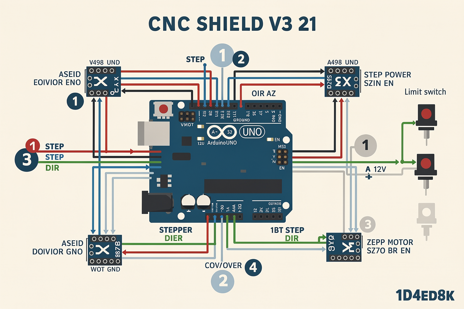
Introduction: From Mechanical Frame to Nervous System
With the mechanical frame of your Arduino CNC machine built and aligned, it’s time to breathe life into it by installing the electronics. This is where the wiring and electronics setup turns a rigid structure into a responsive, G-code–obeying machine. A clean, well-planned wiring job not only ensures reliable operation but also prevents electrical noise, overheating, and accidental shorts—issues that can ruin a project and waste hundreds of rupees in components.
In this section, we’ll cover the full electronics chain: from choosing the right Arduino board and stepper drivers, through wiring the CNC shield, to connecting motors, limit switches, and a spindle. By the end, you’ll have a fully wired controller ready to accept GRBL firmware and execute your first movement commands. If you prefer a ready-to-assemble kit, platforms like TecnoMate offer bundled electronics packages with genuine components and datasheets, saving you the hassle of sourcing individual parts from multiple vendors.
Core Electronics Components for an Arduino CNC Machine
Before picking up a soldering iron, gather the following key parts. The list below is based on the most common DIY CNC controller setup (Arduino + GRBL + CNC Shield) used by makers worldwide, as seen in popular builds like the “DIY CNC Controller” guide from DIYMachining and the “Full-Size CNC for €500?!” YouTube project.
| Component | Typical Specification | Purpose |
|---|---|---|
| Arduino Uno (or Nano) | ATmega328P at 16 MHz | Runs GRBL firmware, receives G-code, drives stepper signals |
| CNC Shield v3 or gShield | 4-axis (X,Y,Z,A) with pin headers | Breaks out Arduino pins to stepper drivers, limit switches, spindle |
| Stepper Drivers | A4988 or DRV8825 | Converts step/direction pulses into coil current for stepper motors |
| Stepper Motors | NEMA17 (1.8° step angle, 2–3 A) or NEMA23 for larger builds | Moves each axis; torque and current depend on frame size |
| Power Supply | 12V–36V DC, 5–10 A (depending on motor current) | Provides energy to stepper drivers and spindle |
| Limit Switches | Mechanical or optical, NC (normally closed) | Homing and end-stop detection; prevents over-travel |
| Spindle / Spindle Motor | 775 DC motor with ER11 collet or 500 W BLDC + VFD | Cuts material; can be controlled via GRBL’s PWM pin |
| Wiring, Connectors, Fuse | 18–22 AWG stranded wire, screw terminals, blade fuse holder | Secure connections, overcurrent protection |
Note: NEMA23 motors (as used in the “DIY CNC router | Arduino + GRBL + NEMA23” build) typically require 24–36 V supplies and higher-current drivers like the TB6600. Most desktop machines work well with NEMA17 + A4988.
Step-by-Step Wiring Guide
1. Mount the CNC Shield on Your Arduino
Begin by pressing the CNC shield (v3 or gShield) onto the Arduino Uno’s headers. Ensure the shield is aligned correctly—most boards have a silkscreen arrow indicating the “Uno” end. For the gShield, screws and standoffs are included to secure it. If you’re building a large CNC router (like the one in the €500 project), you may need a separate breakout board and parallel wiring, but for Arduino-based machines, the shield keeps everything compact.
Pro tip: Use a multimeter to verify that no shield pins are bent or shorting to adjacent pins before powering up.
2. Install Stepper Driver Modules
Insert the stepper drivers (A4988 or DRV8825) into the sockets on the CNC shield. Orientation matters – the driver’s “enable” pin (often marked with a dot) must face the center of the shield or the microcontroller. For A4988 drivers, set the microstepping jumpers under the driver to your desired resolution:
- No jumper = full step (200 steps/rev)
- Jumper on MS1 = 1/2 step (400)
- MS1+MS2 = 1/4 step (800)
- MS1+MS2+MS3 = 1/16 step (3200) – recommended for smoother motion.
GRBL v1.1 default settings assume 1/8 microstepping (jumpers on MS1 and MS2) commonly used with the shield v3.
3. Connect Stepper Motors
Each stepper motor has two coils (usually colour‑coded: A+ black, A- green; B+ red, B- blue). Wire them to the stepper driver’s terminal block (2B, 2A, 1A, 1B) in the correct order. If the motor runs in the wrong direction later, swap one coil pair (e.g., swap A+ and A-). Secure wires with screw terminals.
For a 3‑axis machine, connect X motor to the X socket, Y to Y, and Z to Z. Some shields include a fourth axis (A) for a rotary attachment.
4. Power Supply Wiring
A common mistake is undersizing the power supply. Each NEMA17 motor running at 1 A RMS draws ~1.2 A from the supply (accounting for driver efficiency). Three motors + Arduino + spindle could draw 4–5 A. For a 24 V system (recommended for better torque at higher speeds), use at least a 6 A supply.
- Wire the supply positive (+) to the shield’s power input terminal (marked Vmot or 12–36 V). Negative (–) to GND.
- Add a fuse (e.g., 5 A or 10 A blade fuse) on the positive line near the supply – this protects your electronics from accidental short circuits.
- Use 18 AWG stranded wire for motor power; thinner wire for signal wires is fine.
Safety note: Never connect or disconnect stepper motor cables while power is on—the back‑EMF can damage the drivers.
5. Limit Switches and Homing
GRBL supports up to six limit switch inputs (X, Y, Z, plus for each end). Most machines use normally closed (NC) switches wired in series for each axis, so that a triggered switch opens the circuit and signals an error. The CNC shield has dedicated limit‑switch pins:
- X limit → D9
- Y limit → D10
- Z limit → D11
Connect one wire from the switch common to the shield’s limit pin, and the other to GND. For NC wiring, you’ll need to enable pull‑up resistors in GRBL settings (or activate internal pull‑ups via the $5 parameter). Many builders use standard micro‑switches from electronics stores; for a cleaner build, use shielded cable to prevent noise.
6. Spindle Control (Optional but Recommended)
If you’re using a DC spindle (e.g., 775 motor), you can control its on/off speed via GRBL’s spindle enable (pin D12) and PWM (pin D11 on v3 shields). Wire a MOSFET or relay module between the spindle power line and the shield’s spindle pins. For laser engraving, the same PWM pin controls the laser power. Always include a flyback diode across a DC motor to suppress voltage spikes.
Verifying Your Connections
After all wires are routed and fastened, perform a visual continuity check:
- No solder bridges or stray wires touching adjacent pins.
- Stepper motors are correctly paired (check resistance between each pair of wires – should be ~2–5 Ω for NEMA17).
- Limit switches close the circuit when pressed (using continuity mode on your multimeter).
Power up without a computer – just the supply. The Arduino’s green LED should light. Listen for any buzzing from the stepper drivers; a constant high‑pitched whine indicates the drivers are enabled but no step signal is being sent – this is normal. If you smell burning or see smoke, immediately disconnect power and re‑check your wiring.
Flashing GRBL and Initial Testing
Now, connect the Arduino to your PC via USB. Download the latest GRBL firmware (v1.1h) from the official GitHub repository or use the Arduino IDE’s library manager. Upload the firmware as you would a normal sketch. Once uploaded, open a serial monitor (115200 baud) and type $$ – you should see a list of GRBL parameters. This confirms the controller is alive.
Send a simple G‑code command like G1 X10 F100 (move X axis 10 mm at 100 mm/min). The motor should turn smoothly. If not, check motor wiring or driver current limits (adjust the pot on the A4988/DRV8825 – turn clockwise to increase current, but never exceed the motor’s rated current).
Sourcing Your Electronics in India
Finding genuine stepper drivers and compatible CNC shields can be hit‑or‑miss on general e‑commerce sites. Many Indian makers turn to specialized platforms that stock pre‑tested electronics. TecnoMate offers a “Arduino CNC Controller Kit” that includes an Arduino Uno, CNC shield v3, four A4988 drivers, a 12 V 5 A supply, and wiring accessories—all with datasheets and a build guide. This reduces the risk of mismatched components and saves time debugging.
Final Checks Before Cutting
Before declaring your wiring complete:
- Secure all cables with zip ties to avoid snagging during rapid moves.
- Double‑check ground loops – all power grounds should tie back to the supply’s negative terminal.
- Test limit switches – issue a
$Hcommand to perform a homing cycle; each axis should jog until it contacts the switch, then back off. - Measure motor temperature – if drivers get too hot to touch (over 60°C), increase heat sinking or lower the current trim pot.
With your electronics wired and tested, you’re ready to move on to software calibration and first cuts. Remember: a clean electronics setup is the foundation of a reliable CNC machine—rush this step, and you’ll spend hours chasing ghost movements later. Take your time, and enjoy the process of turning bare wires into a machine that follows your every command.
Software Setup: GRBL & G-Code
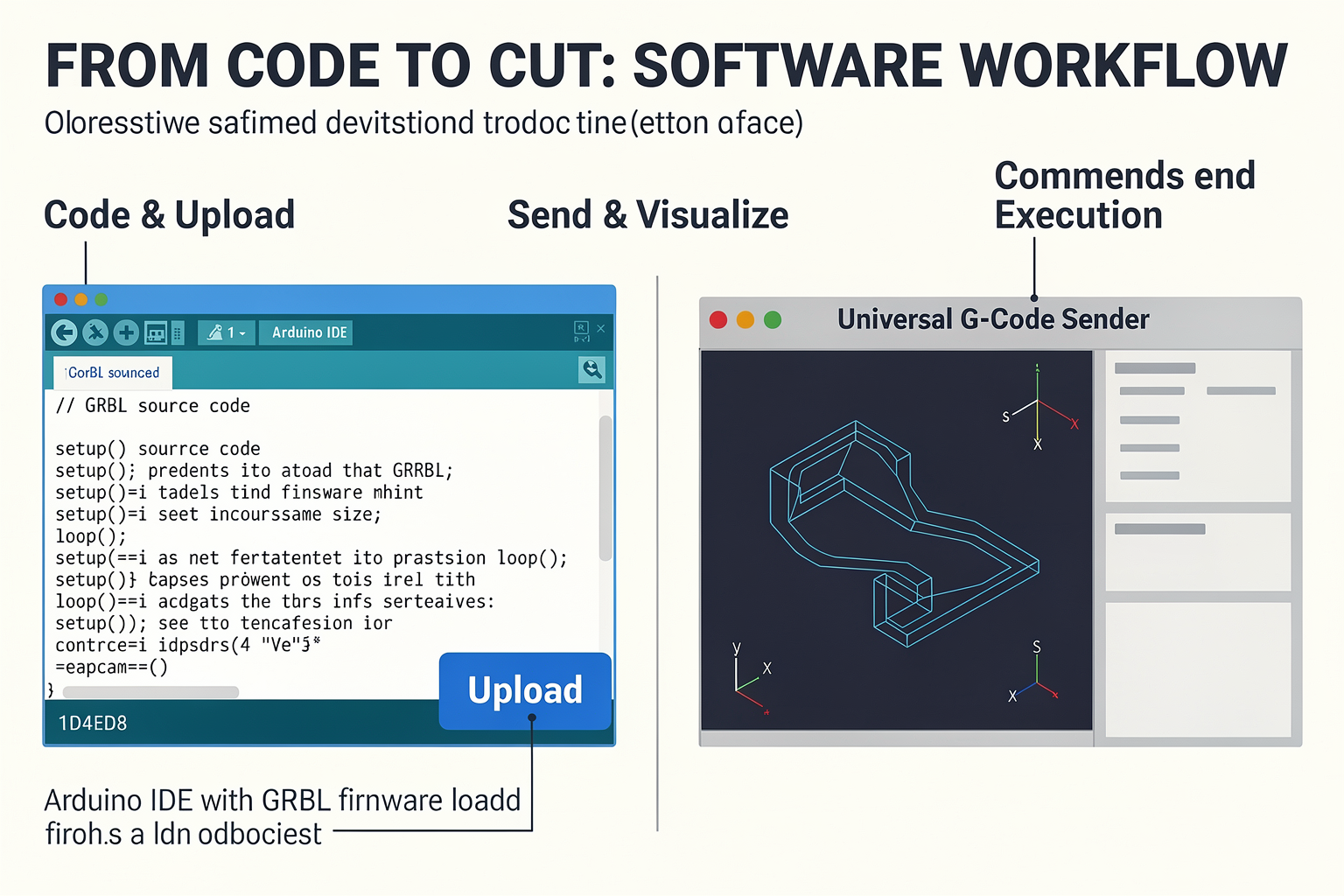
Introduction to GRBL: The Brain of Your CNC
Now that your Arduino CNC machine is wired and ready, it’s time to breathe life into it. The software layer is what turns raw stepper motor pulses into precise, repeatable cuts. At the heart of most DIY Arduino CNC machines is GRBL — an open-source, high-performance firmware that runs directly on the Arduino Uno or Mega. GRBL interprets G-code (the standard language for CNC machining) and converts it into timed step-and-direction signals for your stepper drivers. It’s the same firmware used in countless hobbyist builds, from simple drawing machines to full-size routers (as seen in builds like the €500 CNC project on YouTube [1]).
GRBL is lightweight, real-time, and capable of handling up to 30 kHz step pulses, which is more than enough for NEMA17 or NEMA23 motors on a desktop router. For most DIY projects, you’ll flash GRBL 1.1 (the latest stable version) onto an Arduino Uno. The firmware includes a command-line interface via the Arduino’s serial port, allowing you to configure parameters, home axes, and jog the machine before sending actual G-code jobs.
Flashing GRBL to Your Arduino
Step 1: Download the GRBL source code.
Head to the official GRBL GitHub repository (github.com/grbl/grbl) and download the latest release as a ZIP. Alternatively, you can clone the repository using Git.
Step 2: Install the GRBL library in the Arduino IDE.
- Open the Arduino IDE (version 1.8.5 or later is fine).
- Go to Sketch → Include Library → Add .ZIP Library… and select the downloaded GRBL ZIP file.
- The library will appear under File → Examples → grbl → grblUpload.
Step 3: Upload to your Arduino.
- Connect your Arduino Uno via USB.
- Select the correct board and COM port under Tools.
- Open the
grblUploadexample sketch. It’s a single empty file that simply includes the GRBL library — the actual firmware is compiled and uploaded automatically. - Click Upload. After a few seconds, you’ll see “Done uploading.”
Step 4: Test the connection.
Open the Serial Monitor (set baud rate to 115200). If GRBL is running, you should see a welcome message: GRBL 1.1f ['$' for help]. Type $ and press Enter to list all available commands. This confirms the firmware is alive and ready to configure.
Configuring GRBL: Setting Up Your Machine’s Parameters
Every CNC machine is different — different lead screw pitches, pulley ratios, microstepping settings, and axis travel limits. GRBL stores these parameters in non-volatile memory using a set of $ commands. You’ll need to adjust at least the following critical values:
| Parameter | Command | Example Value | Meaning |
|---|---|---|---|
| Steps per mm (X) | $100 | 80.0 | Number of stepper motor steps needed to move 1 mm on X-axis |
| Steps per mm (Y) | $101 | 80.0 | Same for Y-axis |
| Steps per mm (Z) | $102 | 80.0 | Same for Z-axis |
| Max travel (X) | $130 | 300.0 | Maximum X-axis travel in mm (set to your machine’s limit) |
| Acceleration (X) | $110 | 500.0 | Acceleration in mm/s² (start conservative, e.g., 200) |
| Max feed rate (X) | $120 | 500.0 | Maximum speed in mm/min |
How to calculate steps per mm:
$$ \text{Steps per mm} = \frac{\text{Motor steps per revolution} \times \text{Microstepping}}{\text{Lead screw pitch (mm/rev)}} $$
For example, a NEMA17 motor with 200 steps/rev, 1/16 microstepping on a driver like A4988, and a lead screw with 2 mm pitch:
(200 × 16) / 2 = 1600 steps per mm.
Send each $ command via the Serial Monitor to update the value. Use $$ to view all current settings. Once you’ve set them, send $ again and confirm.
Important: Save your settings by sending $ (no argument) — GRBL auto-saves after each $XX=value command.
Sending G-Code: From Design to Movement
GRBL speaks G-code, a standardized language (RS-274) that tells the machine where to move, how fast, and when to turn the spindle on/off. Here are the essential commands you’ll use:
- G0 – Rapid positioning (move fast to a point without cutting)
- G1 – Linear interpolation (controlled feed rate for cutting)
- G90 – Absolute positioning (positions are from machine origin)
- G91 – Incremental positioning (positions are relative to current location)
- M3 – Spindle on clockwise
- M5 – Spindle off
For example, a simple G-code program to cut a 50 mm square at 500 mm/min:
G21 ; Set units to mm
G90 ; Absolute positioning
G0 X0 Y0 Z5 ; Move to start position above workpiece
G1 Z-2 F100 ; Plunge 2 mm deep at 100 mm/min
G1 X50 F500 ; Move right
G1 Y50 ; Move up
G1 X0 ; Move left
G1 Y0 ; Move back to start
G0 Z5 ; Retract
M5 ; Spindle off
Sending the code:
Use a GRBL sender application. Popular free options include:
- Universal G-Code Sender (UGS) – cross-platform, feature-rich
- Candle – lightweight Windows GUI
- bCNC – Python-based with advanced features
Upload your G-code file (generated from CAM software like Fusion 360, Easel, or Carbide Create) and click “Send.” The sender will stream the commands line by line, monitoring real-time status and position. Many senders also display the toolpath preview, which is extremely helpful for verifying before actually cutting.
Putting It All Together: Your First Test
Before committing expensive material, run a dry run with the Z-axis raised. Load a simple G-code file (like the square above) and watch the axes move. If everything looks correct, lower the Z to touch a piece of scrap and run the same program to carve a shallow line.
Where TecnoMate Fits In
If you’re building your first CNC controller and don’t want to hunt down every component separately, TecnoMate offers complete Arduino-compatible bundles that include a pre-flashed GRBL Arduino Uno, a CNC shield with A4988 drivers, power supply, and even a step-by-step guide. You can source a tested kit for this build from platforms like TecnoMate, which ships genuine components with datasheets across India. That way, you can focus on configuration and cutting rather than debugging hardware compatibility.
With GRBL running and your machine responding to G-code, you’ve successfully crossed the software finish line. Next, we’ll calibrate the machine with a test cut and fine-tune your settings for real-world milling.
Mechanical Assembly & Frame Building
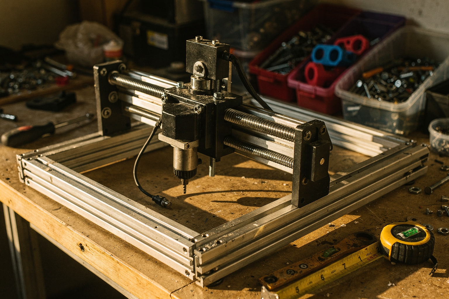
Building the mechanical structure of your Arduino CNC machine is the most critical step; even the most powerful electronics cannot compensate for a wobbly frame. If the gantry twists or the table flexes under weight, your cuts will be inaccurate. Most DIY enthusiasts in India opt for an X-Y Bridge style design, where a "gantry" (the carriage that holds the spindle) rides across a bed. This approach balances rigidity with manageability.
Choosing Your Material: Aluminum vs. Wood
The backbone of your CNC will either be an aluminum extrusion profile—usually the 20x40 or 40x40 4040 aluminum extrusion—or a combination of high-density plywood. While wood is cheaper and easier to glue, aluminum is far superior for stiffness and vibration dampening. If you are using the extrusion method, you will need to construct the table and the gantry sides separately and then interlock them.
However, if you opt for a more advanced full-size CNC for €500 projects often seen trending in 2025, the rule of thumb is a solid metal base or a very high-density workbench setup to prevent the table from "squatting" during cuts. For most home workshops in India, aluminum extrusion remains the gold standard because it screws together effortlessly with T-nuts and bolts, allowing for disassembly if you need to move your machine.
Constructing the X-Axis (The Bedplate)
The first rail you build is the X-axis. This lies flat and holds your workpiece. You will need to cut your selected aluminum rail to size. Precision matters here simply because every extra inch adds weight to the motors.
- Mounting Linear Bearings: You will need to fit the linear bearing blocks onto the rail. Most DIY kits use "seat" bearings—the bearings have a flat side that sits against the rail, while the cylindrical side faces up. You often need to "beat" these bearings onto the rail with a rubber mallet to ensure a firm fit.
- Adding the Lead Screw: The precision rod that acts as the line of movement is mounted on top of the rails. For a beginner, a 2mm 5-start lead screw is the sweet spot. It gives you fast movement (less than 2 minutes to traverse the entire bed) without losing precision.
- The Carriage: This is the sliding block that sits on the top of the rails to support the Z-axis. It needs to be machined to hold the bearing blocks and the Z-axis stepper motor (usually mounted underneath the carriage).
The Gantry and Z-Axis Setup
Now, construct the outer frame that sits on top of the rails. This forms the open square bridge. This section is where the math comes in—you need identical lengths for the gantry rails to ensure that the Z-axis spindle moves up and down perfectly parallel to the cut surface.
Z-Axis Options Deciding how the Z-axis moves is controversial and defines the machine's capabilities.
- Z-Screw (Traditional): A threaded rod is mounted centrally. As the stepper motor rotates, it lifts the spindle. This offers solid precision but is slow.
- Rack and Pinion: If you are building a larger machine (like the €500 full-size CNC mentioned in recent tutorials), a rack and pinion system is often preferred. It’s much faster because a spur gear pins into a toothed metal rail. However, this requires more setup and higher motor torque.
For a plotter or engraver, the Z-screw is standard. For routing wood, the pinion system is better for productivity.
Motor Mounting and Driver Location
Once the frame is together, you must mount the stepper motors. The most common approach for DIYers is to place the motors on the "South-West" corner of the gantry frames and drive the lead screws via pulleys and timing belts. This keeps the gantry light and the drives cool. You have two choices here:
- Direct Drive (Heavy): The motor is mounted directly to the carriage. Great torque, but makes the gantry very heavy.
- Belt Drive (Recommended): The motor is mounted on the side of the gantry and transmits movement via a timing belt (like an AT3 bike chain style). This significantly reduces the weight the motors have to lift, preserving accuracy.
When mounting the drivers and power supply, avoid mounting them on the frame itself. Vibration travels through the frame; if you mount the "boiler" (electronics) next to the frame, the noise will corrupt the stepper signals. Mount them on a wooden desktop or a separate "earth box" nearby.
Managing Dust and Debris
This is an often-overlooked part of mechanical assembly in India, especially during monsoon or dry summers. If you are using a router or spindle, you must design a dust extraction port. Many builders simply bolt a tall bag at the back of the gantry. This not only keeps your workspace clean but also prevents chips from jamming the Z-axis motor.
For those sourcing parts for this project, remembering to buy backup M3 and M4 nuts and washers is vital. Aluminum threads can get chewed up, and cross-threading is a common issue when tightening down the frame. Having a "parts jar" of generic hardware during assembly can save you several hours of frustration.
Sourcing these specific components—like precise linear shafts or branded stepper drivers—can be a hassle when you are disconnected from the supply chain. Platforms like TecnoMate offer ready-to-build project kits and genuine components for projects like this. By providing genuine components with datasheets and step-by-step build guides, TecnoMate helps ensure your mechanical assembly starts with high-quality, verified parts rather than off-brand hardware that might seize or strip.
Frame Bracing
Finally, once the Z-axis moves freely on both sides, you must think about deflection. If you lean on the gantry and it bows, the spindle moves with your hand. To fix this, you may need to add "cross bracing" using angle brackets. This transfers the weight of the moving head onto the fixed frame legs, not the bed itself.
With the frame complete, you have a rig that is stiff enough to cut plywood cleanly. The next steps involve translating that physical movement into digital commands by wiring the motors to your Arduino.
Calibration & First Cuts
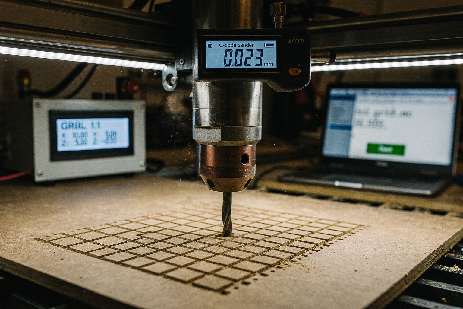
Flashing the Firmware (GRBL)
At this stage, your machine is physically assembled, and the wiring is done, but it isn't alive yet. The brain of your Arduino CNC controller is the firmware, and for 99% of DIY projects, this is GRBL. GRBL is an open-source, high-performance firmware for controlling "CNC machinery," designed initially for the Arduino microcontroller platform. It is lightweight, efficient, and capable of handling complex G-code inputs, making it the industry standard for projects ranging from simple drawing plotters to large-format routers.
To introduce this software, you will typically pair your Arduino (often an Uno or Mega) with a CNC shield like the gShield mentioned in the DIY machining community. As detailed by many build guides, setting up a DIY CNC controller using this specific pairing has been shown to cost less than $80 while offering significant performance. Before you can customize the machine, you must flash the firmware.
- Download GRBL: Go to the official GRBL repository on GitHub and download the latest stable release for ARM (if using gShield) or AVR (if using standard Arduino).
- Open IDE & Upload: Open Arduino IDE, point it to the downloaded folder, and select the
grbl.inofile. - Connect: Hook up your Arduino via USB to the PC. Ensure the baud rate in your serial monitor is set correctly (usually 115200 baud).
- Verify Upload: Click "Upload". Once complete, look at the Serial Monitor. It will return a status report, often starting with "Grbl 1.1h ['$' for help]".
Initial Configuration (The Startup Commands)
Now that the brain is online, you need to tell it how your body is built. This configuration occurs via the G-code command interface (usually accessed through software like Universal G-Code Sender, Pronterface, or Arduino IDE's serial monitor).
Calibration begins with the startup lines setting. By typing $1 into the terminal and hitting enter, you can define the first two lines of code that GRBL executes whenever it reboots. Standard practice is to tell it to report the status automatically. For example, changing $1=28 tells GRBL to attach a status report to boot-up, shutting down the machine only if the reset button is pressed—but this is for advanced users.
The critical calibration command is $0= and $1= (Step Pulse Time). If your machine skips steps or buzzes, this is usually the culprit. However, the most important adjustments are Steps Per Millimeter ($0 and $10). These numbers are derived from your stepper motors and lead screws. If it moves too far or too little, you must calculate the steps/mm based on your driver micro-stepping and thread pitch. For instance, a 1.8-degree stepper motor with a 2mm pitch lead screw and 16 microsteps equals 200 * 16 / 2 = 1,600 steps/mm.
TecnoMate offers a curated selection of genuine microcontrollers and stepper drivers. Whether you are building the controller described above or needing specific breakout boards for your build, sourcing verified components from TecnoMate ensures your calibration calculations will align with hardware reality, preventing headaches during the setup phase.
Testing Motor Endpoints & Homing
Before touching the spindle, you must test for mechanical binding and ensure your limit switches work. This is often called the "Jog Test."
- Manual Jogging: Use your control software (like Universal G-Code Sender) to move the X and Y axes slowly. Keep your hand near the spindle or tool tip but NOT touching it. Listen for the motor hum.
- Check Binding: If a motor suddenly stops humming or acts sluggish, the shaft is likely stripped, or the coupler is slipping. This is common if the torque ratings of the drivers don't match the physical exertion required by the frame.
- The Endstop test: Utilize your limit switches. If the machine hits the end of the rail, it should stop. If it runs into the frame, your limit switches are wired backwards or the mechanical alignment is off. Adjust the switches so the machine stops precisely 5mm away from the frame, providing a safety buffer.
The "Gouge" Test: Your First Cut
This is the moment of truth—the First Cut.
Never start with a deep bit or hard material like steel or aluminum on your first run. You will likely experience errors. Start with a "Gouge Test" on a soft material like cardboard, foam, or soft pine wood.
- Material: A square piece of pine or cheap plywood.
- Tool: A hot knife, a scalpel, or a V-bit for marking.
- Depth: Start with a G0 move (rapid position) to a safe tip height, followed by a G1 move (linear movement).
- The Move: In G-code, issue a command like:
G1 Z-0.5 F300(Move down at a feed rate of 300mm/min) followed byG1 X50 Y50.
Observation:
If the cut is straight, clean, and the machine stops exactly where you commanded it, your calibration is successful. If it spins the wrong way, the direction is inverted (use $13=1 for inversion). If the cut is wobbly, your frame is loose. If the cut skips, your steps/mm setting ($0) is wrong.
Common Calibration Failures & Troubleshooting
Even with perfect code, mechanical alignment is key. A very common issue in Indian maker communities when building these from scrap metal is flexing. If your frame bends under the weight of the spindle, the cut quality will be poor no matter how well calibrated.
- The "Sewer Snake" Effect: If the machine moves jerkily (vibrating) rather than smoothly, your acceleration settings (
$2) are likely too high for the current and voltage of your power supply. Lower the acceleration value. - Steps Lost: If the plotter draws a straight line but comes back at the end of the loop off by a few millimeters, you have "steps lost." This usually happens if the V-bit missed the material during the deep plunge. Reset the G-code control to Z+ (up) immediately.
- Spindle Sync: If using a CNC router, ensure the speed (RPM) matches the material depth. Most DIY setups rely on variable speed power tools—ensure you have a foot pedal control or a safe method to start the tool only after the spindle is up to speed and positioned correctly.
Source data from building CNC routers indicates that while the project can cost as little as €500 ($500+), the value lies in the learning curve. As one Maker on Reddit noted after completing a lengthy CNC build using Arduino and GRBL: "It is a massive project, but the satisfaction of seeing the machine plot your first lines is unmatched."
Once you have mastered these commands, running your own G-code files to cut acrylics, PCB panels, or artistic contours is just a file transfer away. Just remember: always verify directions and clear the area around the machine before hitting "Run."
Impact & Implications
The Democratization of Manufacturing
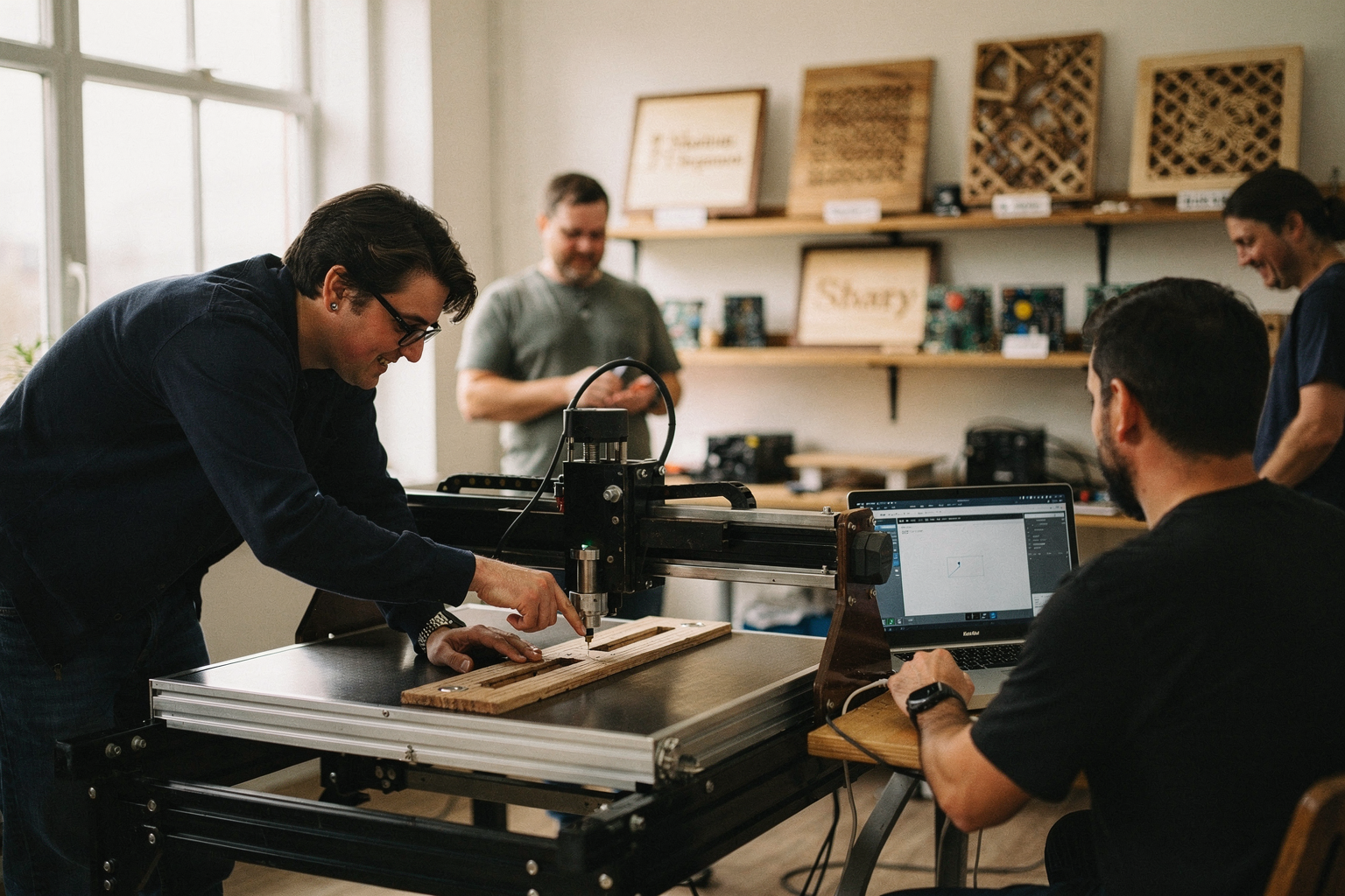
Building an Arduino-based CNC machine represents a fundamental shift in how we view accessibility to manufacturing tools. Historically, computer numerical control (CNC) machinery has been the domain of industrial workshops or large companies, requiring a significant capital investment on the order of tens or hundreds of thousands of rupees. However, the implications of the "DIY CNC movement" are profound: they are democratizing precision. By leveraging open-source hardware and community-driven design, a hobbyist can replicate industrial functionality at a fraction of the cost.
The economic implications of this engineering feat are best illustrated by global community projects. For example, one popular online tutorial demonstrates that it is not only possible but practical to build a full-size, powerful, and fast CNC machine for approximately €500 (roughly ₹45,000 at current exchange rates) [1]. This figure is staggering when compared to the entry-level price tag of commercially available desktop CNC routers, which often start well above ₹1,00,000. When broken down, this economic model shifts the expense from the "machine itself" to the user's time and effort. By using an Arduino as the central processing unit, builders avoid licensing fees and proprietary controller restrictions that plague commercial machines.
Furthermore, the cost of the electronic brain—the controller—can be approached from a budget-conscious perspective. Guides often detail how users can build their own DIY CNC Controller setups using an Arduino and a specific shield, such as the gShield, for less than $80 (around ₹6,600) [2]. This breakdown of costs implies that an entire motion control system can be sourced for a similar price to a single mid-range component from an industrial supplier. For a student in India, this means engineering projects are no longer limited by a lack of funds for exotic equipment; instead, the barrier to entry is lowered to the cost of raw materials and basic electronics, which are readily available in local markets or via specialized e-commerce platforms.
Evolution from Hobbyist to Engineer
Implications of this project extend beyond financial savings; they represent a critical evolution in skill acquisition. Constructing a CNC machine is arguably one of the most rigorous embedded systems projects a hobbyist can undertake. It forces a transition from basic "Digital Input/Output" tasks—like blinking an LED—to complex closed-loop systems that interpret coordinate geometry.
The core of this build is the printer firmware known as GRBL (GNU Float RBL). Unlike a standard Arduino sketch, GRBL acts as a real-time interpreter. It bridges the gap between "human-readable" code (G-code) and "machine-readable" pulses. This electrical implication requires a deep understanding of pulsewidth modulation (PWM) and timing. As mentioned in comprehensive guides on the subject [6], the machine must handle inputs that coordinate three distinct axis movements simultaneously without losing synchronization. This implies that builders must have a working knowledge of directional control and stepping logic, concepts often learned in advanced electronics labs.
In addition to software proficiency, the build fosters mechanical aptitude. The dynamic implications of using a standard Arduino Uno with simpler servo motors are often addressed by upgrading to NEMA 23 stepper motors, which are larger and provide more torque than standard hobby steppers [2]. This decision has a direct impact on the machine's rigidity and stability. The builder starts making engineering trade-offs: Is a faster, lighter frame better because it reduces milling time, or should one prioritize a thicker aluminum frame to reduce vibration? These are not trivial questions; they are the fundamental problems an industrial engineer solves daily. By struggling through the decoupling of mechanical friction and electrical synchronization, the builder effectively upskills alongside the machine.
Systems Thinking: Mechanical, Electrical, and Firmware Integration
One of the significant implications of this build is the requirement for "systems thinking." A successful CNC machine does not function as a sum of its parts (a stepper motor, a driver, a microcontroller); it functions as a single, integrated system. If one part is weak, the whole system fails. This is evident when observing the limitations of low-cost builds. A full-size CNC machine might be built for €500, as guide [1] suggests, but achieving high precision is difficult without addressing noise and vibration.
Consider the implications of using an L293D motor control chip. While standard L293D chips were originally designed for basic DC motors, their application in CNC routing is limited by heat dissipation and current handling [8]. Implications here dictate that builders must often upgrade to modern drivers like the A4988 or TMC2208, or use a shield like the gShield with stronger drivers. This means a beginner might start with simple code but quickly hit a physical wall. The implication is that resources like PCBSync [6] or DIYMachining [2] become critical reading material; they serve as blueprints not just for wiring, but for troubleshooting the interplay between electrical heat and mechanical load.
Moreover, the electrical implication of running multiple relays (for spindle control and limit switches) cannot be understated. A CNC machine driven by an Arduino is rarely silent. It hums with the whine of step motors. This implies that power supply design is as important as code implementation. Poor power supply design leads to "step loss," where the Arduino loses track of the stepper motor's position. The ability to diagnose these data integrity issues is what separates a toy project from a functional machine.
Versatility and Project Evolution
The aesthetic and functional implications of an Arduino CNC machine are its versatility. Unlike a drone, which has a singular purpose (flight), or a simple robotic arm, which usually has one motion range, a CNC machine adapts to the user's needs. The implications here are immense for a maker's workshop. A CNC drawing machine, for instance, used for prototyping parts or sketching, requires very specific mechanical tolerances and smooth motion [4].
However, the implications of the NEMA 23 steppers often mentioned in tutorials suggest that the same hardware, if framed correctly, can transition into a CNC router [1]. This shift implies a design for change. The frame built initially for engraving acrylic might be reinforced for milling aluminum—a transition that requires significant mechanical upgrading (often changing Acetal (Delrin) smooth rods to precision linear rails). This highlights the versatility of the concept but also the need for forward planning.
For those interested in production-level outputs, the build can be adapted for laser engraving. The implications of a laser module are twofold: safety and focus. The Arduino acts as the gatekeeper, cutting the power to the laser only when movement coordinates are entirely within the worksafe area. This software safety layer implies that the Arduino is not just a controller but a safety mechanism. It reinforces the idea that the Arduino CNC project is a stepping stone towards complex manufacturing centers, potentially replacing expensive plotter machines for technical drawing tasks within a few months of experimentation [4].
Sourcing Components and Resources in India
While the technical implications are rewarding, the logistical implications of sourcing parts for a project of this magnitude are a significant hurdle for the Indian engineering enthusiast. Global tutorials often list component sources in USD or Euros, presenting a barrier for local builders who need to comply with import duties, lead times, and voltage compatibility (220V AC in India vs 110V in many US tutorials).
This is where the local ecosystem plays a crucial role. While a €500 build might seem accessible once the dollar conversion is factored in, the anxiety of sourcing a specific $50 driver board or a $40 Arduino clone amidst availability issues is real. For builders looking to avoid the headache of importing individual components—especially those with strict tolerance requirements like steppers and limit switches—reliance on curated local supply chains is increasingly important.
Platforms like TecnoMate offer a pragmatic solution to this fragmentation. For complex builds like this, the implication is clear: time is money. Debugging a wiring harness or a stepper setup takes longer than simply unpacking a pre-tested kit. TecnoMate bridges the gap between the disorganized electronics marketplace and the disciplined requirements of an engineering project. By providing genuine components—such as reliable Arduino boards and motor drivers—alongside the technical datasheets necessary to verify that a component matches the theoretical requirements of your build (like a specific current rating for a driver), TecnoMate ensures that the builder can focus on the GRBL programming and frame construction rather than "Is this board actually functional?"
Finally, the post-build impact involves the community. As seen on Reddit, makers are often compelled to write extensive guides because the information available is so fragmented [5]. The implication of this community sharing is that the knowledge base is growing rapidly. What was considered a "top-secret" project a decade ago is now a standard curriculum for engineering students. Ultimately, the impact of this Arduino CNC build is that it places the power of precision engineering directly into the hands of the individual, turning the concept of "making" from a factory process into a personal journey of hardware and software mastery.
Expert Opinions
The Economics of DIY CNC
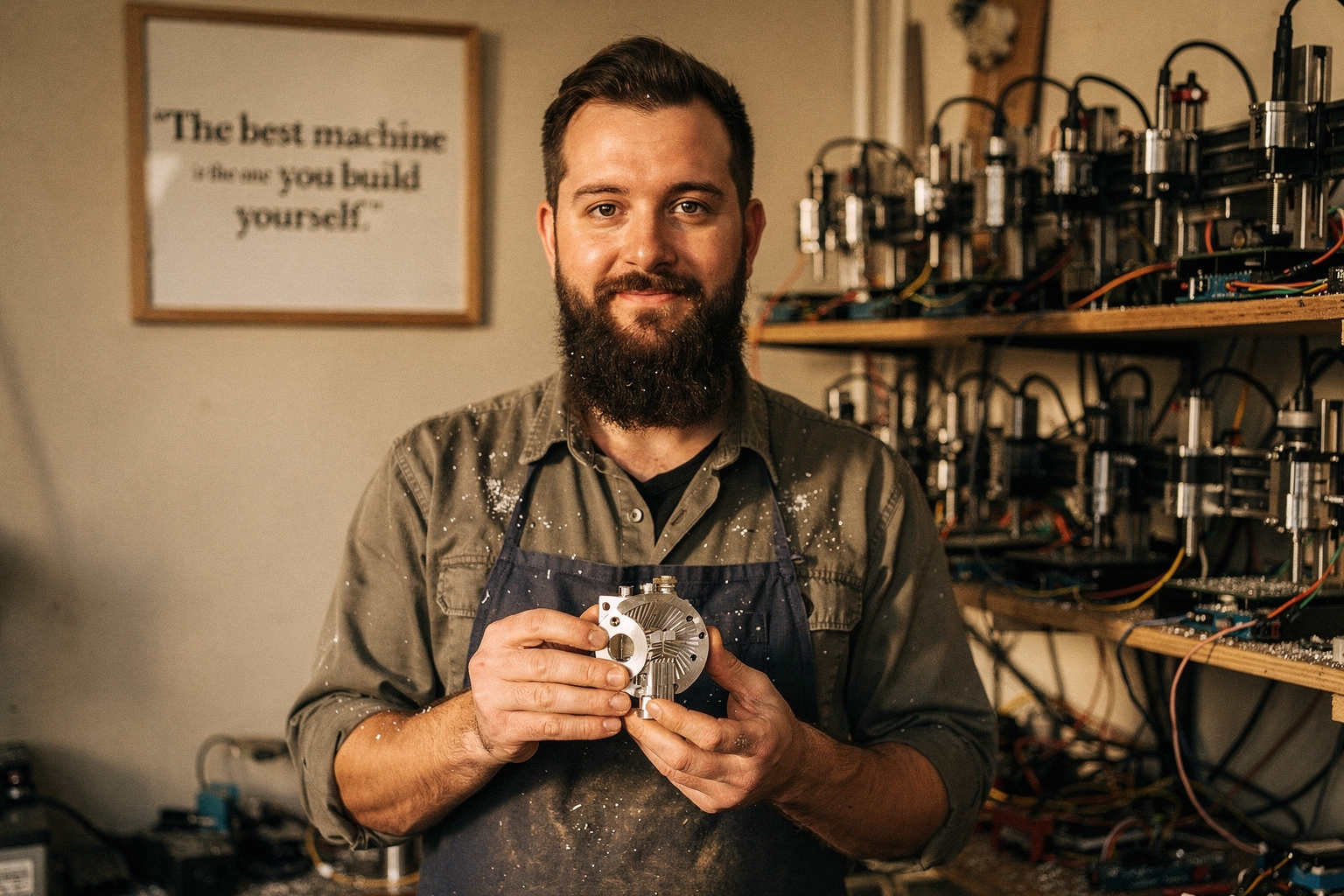
The prevailing sentiment among veteran makers in the Arduino community suggests that the barrier to entry for Computer Numerical Control (CNC) fabrication has been drastically lowered. One of the most controversial yet encouraging statistics to emerge recently comes from the "Full-Size CNC for €500?! Step-by-Step Guide" on YouTube, viewed by Mindsparx over 606,000 times. This figure challenges the long-standing notion that CNC machines are prohibitively expensive industrial tools reserved for corporate workshops. Expert opinion regarding the financial viability of these builds typically highlights that a full-size machine capable of serious routing and cutting doesn't necessarily require a €5,000 budget anymore; it can be achieved closer to €500 if the design focuses on essential functionality over industrial excess.
However, this economic shift does not imply a sacrifice in quality or capability. Experts often point out that "full-size" in this context refers to the active working area of the machine, not necessarily the physical footprint of industrial-grade monster routers. The key takeaway from these analyses is that open-source hardware drivers have democratized precision manufacturing. When planning a project like this, cost management is critical, and sourcing components efficiently becomes a project in itself. Platforms like TecnoMate simplify this by aggregating verified components that meet the stringent specifications required to keep those DIY CNC builds running smoothly.
The Controller Revelation: gShield and GRBL
When discussing the brain of the operation, the overwhelming consensus among technical experts revolves around the integration of the Arduino microcontroller with a dedicated driver shield. According to tutorials posted on diymachining.com, a robust DIY CNC controller can be constructed using an Arduino paired with a gShield for a total cost of less than $80. This is a critical data point for hobbyists in India, where the relative cost of importing specific drivers can fluctuate. Experts emphasize that the combination of an Arduino Uno (or compatible!) with the gShield offers the perfect balance of computational power for real-time G-code interpretation and hardware cost-efficiency.
Furthermore, the software layer is widely cited as a differentiator. The GRBL software library is frequently cited as the gold standard for Arduino-based CNC control. While the Arduino Forum discusses the basics of stepping motors, pointing to the classic L293D chip used for hobby robotics, expert consensus quickly evolves toward specialized stepper drivers for CNC. The gShield simplifies this by handling the complex interrupt timing required for smooth motion, something a standard L293D implementation on a breadboard struggles to manage effectively at higher speeds. This reliance on open-source ecosystems allows anyone with a $80 harness to control sophisticated multi-axis movements.
Mechanical Horseshoes: Motor Selection and Build Stability
While software drives the machine, mechanical engineering determines the final product's accuracy. In the Reddit community, long-time users often share anecdotes validating the build reliability of Arduino CNC machines. One user recently reported finishing a "big project," building a CNC-machine from scratch using an Arduino Uno and GRBL, noting that with proper calibration, the results are indistinguishable from commercial units. This validation extends to the choice of steppers. The video "DIY CNC router | Arduino + GRBL + NEMA23" underscores the technical preference for NEMA23 motors over the smaller NEMA17s for routers. The rational provided by experts is torque; a router application requires higher torque to maintain feed rates under load, a feat small steppers often struggle to perform silently.
Conversely, for lighter applications such as 3D pen plotting or 2D drawing, experts looking at resources like diymachines.co.uk suggest that the build complexity can be reduced significantly. Opinions here often categorize the machine into two distinct tiers: the heavy-duty router (NEMA23) and the precision plotting machine (NEMA17 or smaller). Choosing the right motor size is a signature debate in the Arduino CNC community, with the consensus firmly favoring oversizing the motors slightly over undersizing them. Oversizing ensures that once the machine is accelerated to a cutting speed, it has enough torque reserves to overcome friction and material density without stalling.
Specialized Applications and Design Adaptation
Expert voices also agree that the "one size fits all" approach rarely works well in CNC. The community is split, functionally, between milling and engraving. While one camp focuses on the heavy-duty router capability demonstrated in the €500 build guides, others focus on the elegance and simplicity of the drawing machine. A recent comprehensive guide from diymachines.co.uk outlined how to build a "simple and high quality CNC drawing machine to draw on almost anything." The expert consensus here is that for a beginner—or someone learning the ropes—starting with a plotting machine (often driven by smaller steppers like NEMA17 or even smaller) is the optimal pedagogical strategy.
Drawing machines eliminate the noise and vibration issues associated with heavy-duty routers, making them ideal for indoor workshops. However, the laser engraving application sits in the middle, requiring the precision of a plotter but the optical power of a routing CNC. In India’s maker ecosystem, where electricity stability and workshop noise ordinances can be factors, the "expert recommendation" often leans toward the drawing/plotters for residential spaces. For those in Tier 2 and Tier 3 cities looking to mimic these international successes, finding a localized source for these specific project components is vital, which is where centralized marketplaces like TecnoMate become incredibly valuable.
Community Validation and Long-Term Usability
Perhaps the most reliable data available comes from the community itself. The sentiment expressed in a recent Reddit thread where a user finished a "latest big project" resonates with nearly every expert contributor to the Arduino Forum. The forum, specifically the thread titled "Building a CNC machine," reinforces that an almost identical process was demonstrated a decade ago when connecting a stepper motor to the same Arduino and L293D chip. This long history of success proves that the physics hasn't changed, even if the components have gotten more refined.
The expert opinion here is that CNC machines are "set it and forget it" tools, provided the initial setup is followed correctly. The validity of the build is tested not after a week, but after hundreds of hours of use. Whether the goal is a €500 full-size router or a laser engraver, the recurring advice is to master the basics—GRBL configuration and motor tuning—before adding complex features like automatic tool changers. Studying these success stories helps novice builders avoid common pitfalls, ensuring that their investment in a kit or custom build pays off in precision rather than frustration.
What This Means For You (TABLE)
What This Means For You (TABLE)
You’ve followed the entire build — from selecting an Arduino Uno, wiring stepper drivers, flashing GRBL, to running your first G-code. Now, step back and look at the big picture. What does a DIY Arduino CNC machine actually mean for a maker in India? It’s not just about saving money — it’s about gaining complete control over your tool, learning how motion control works at the component level, and scaling up without vendor lock-in. To put it in perspective, here’s a side-by-side comparison of your DIY build versus a comparable commercial machine.
| Aspect | DIY Arduino CNC (Your Build) | Commercial Equivalent (e.g., hobby CNC) | Practical Takeaway |
|---|---|---|---|
| Total Cost | ₹8,000 – ₹45,000 (€500 full-size build possible – see Mindsparx YouTube guide) | ₹1,20,000 – ₹4,00,000 (basic 3018 to entry-level 6040) | Save 70–90% by sourcing parts yourself |
| Control Board | Arduino Uno + CNC Shield + GRBL firmware (open-source) | Proprietary closed-source controller (e.g., Mach3, proprietary DSP) | Full software freedom; GRBL is constantly updated by community |
| Stepper Motors | NEMA17 or NEMA23 (driven by A4988/DM542 drivers) | Usually NEMA23 with integrated drivers | Easily replaceable; upgrade to closed-loop steppers later |
| Work Area | Custom (e.g., 300×400 mm up to 1000×1500 mm for €500 build) | Fixed (usually 300×180 mm or 400×600 mm) | Build exactly the size you need — no wasted space |
| Spindle / Tool | DC motor or 775 spindle (₹500–₹2,000) or 500W ER11 (₹3,500) | 300–800W water-cooled spindle (₹10,000–₹25,000) | Lower entry cost; upgrade spindle later without replacing entire machine |
| Learning Curve | Steep (wiring, GRBL config, G-code) — but you gain deep understanding | Plug-and-play, but limited troubleshooting knowledge | DIY gives you repairability — you can fix any part |
| Community Support | Huge: GRBL forums, Reddit r/arduino, YouTube build logs | Manufacturer support (often slow, no open schematics) | Endless free help; you are never stuck alone |
| Upgradability | Modular (add Z-probe, laser head, 4th axis) | Usually closed upgrades (expensive proprietary add-ons) | Future-proof: swap to a 32-bit board like Gerbil later |
Why This Matters for Indian Makers
In India, importing a commercial CNC router can double in cost with customs duties and shipping. Building with locally sourced components — linear rails from Mumbai, threaded rods from Delhi, and an Arduino Uno from a local electronics shop — keeps the project affordable and instantly serviceable. One Reddit user (r/arduino) noted they built their entire 3‑axis CNC for under ₹11,000 using a scavenged printer chassis and an Arduino Uno with GRBL. That’s about the price of a single commercial CNC spindle.
Real-world cost example: A full-size 1000×600 mm CNC can be built for approximately €500 (₹45,000) as demonstrated by the Mindsparx YouTube build — a machine that would retail for €3,000+ in Europe. For Indian buyers, that gap is even larger because commercial brands add 18–28% GST + duties.
The Bottom Line
Building your own Arduino CNC is not a compromise — it’s a strategic decision. You sacrifice some initial convenience for customization, repairability, and radical cost savings. Whether you’re a student prototyping PCB enclosures, a hobbyist making wooden signs, or an engineering team learning motion control, the DIY path gives you a machine that grows with your skills.
To make your build hassle-free, consider sourcing a bundled kit. Platforms like TecnoMate (tecnomate.in) offer ready-to-assemble Arduino CNC project kits that include the Uno, CNC shield, drivers, steppers, and step-by-step build guides — with free delivery across India on orders above ₹999. That way, you skip the part-by-part hunt and jump straight to assembling and tuning your machine.
Your DIY CNC is more than a tool — it’s a foundation for endless projects. Start cutting today.
Frequently Asked Questions
A full-si
Ready to start building?
Explore our collection of DIY kits and components. All project components mentioned in this blog are available in our store.
Browse All Projects