

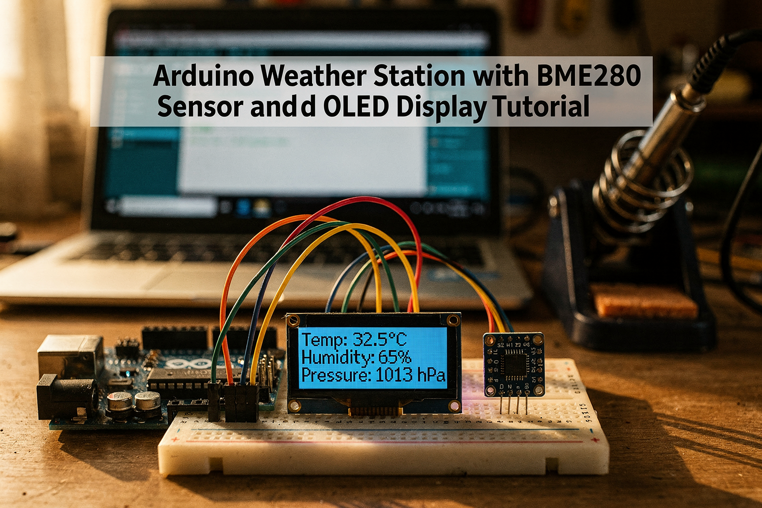
Arduino Weather Station with BME280 Sensor and OLED Display Tutorial
Introduction
Welcome to the exciting world of DIY electronics! In this comprehensive tutorial, we'll build an Arduino-based weather station that measures temperature, humidity, and atmospheric pressure using the BME280 sensor and displays real-time data on an OLED screen. As engineering students in India, understanding weather monitoring systems is crucial not just for academic projects but also for practical applications in agriculture, smart cities, and environmental monitoring.
Weather stations are becoming increasingly important with climate change concerns and the rise of IoT applications. The best part? You can build a professional-grade weather station for under ₹2000 using components easily available in the Indian market. Whether you're a beginner or an intermediate Arduino enthusiast, this project will help you understand sensor integration, LCD display programming, and data visualization.
Throughout this tutorial, I'll guide you through every step with practical insights from my experience working with electronics projects across India. We'll use affordable components from local suppliers, making this project perfect for budget-conscious students while maintaining professional-quality results.
Components Required
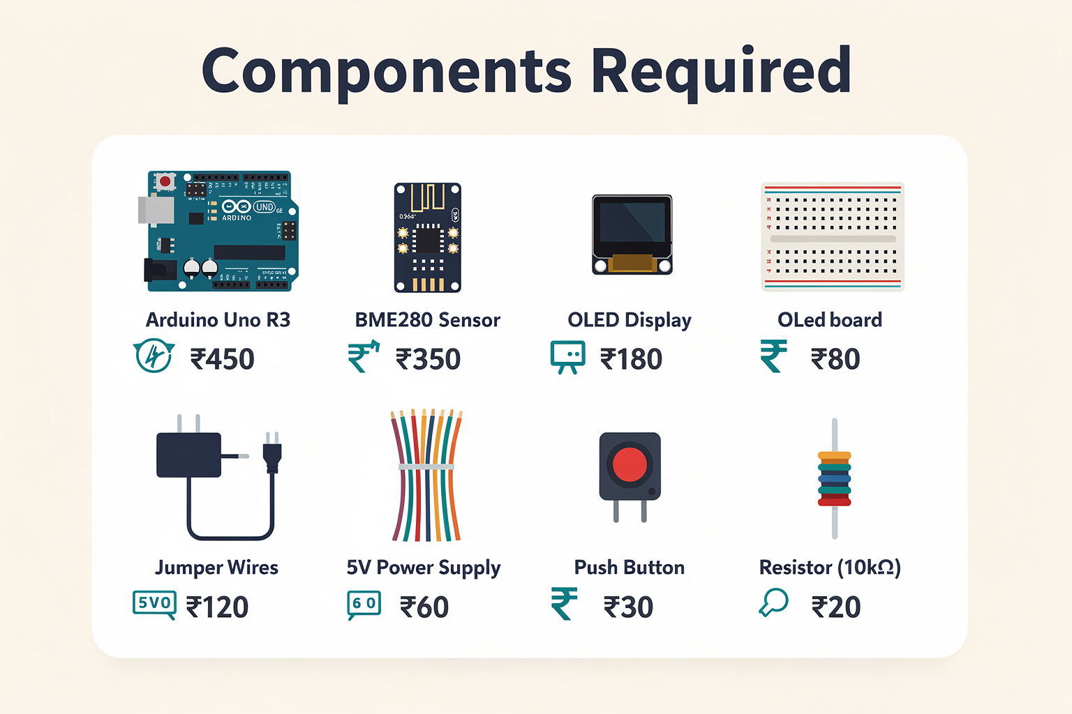
Let's start by gathering all the necessary components. Most of these are readily available at your local electronics market or through online platforms like TecnoMate, Amazon India, or Robu.in.
| Component | Specification | Price (₹) | Availability |
|---|---|---|---|
| Arduino Uno R3 | ATmega328P, 14 digital I/O | 450 | Local store, online |
| BME280 Sensor Module | Temp, Humidity, Pressure | 350 | Tech shops, online |
| 0.96" I2C OLED Display | 128x64 resolution | 180 | Electronics market |
| Breadboard | 400 tie points | 80 | Anywhere |
| Jumper Wires | M-M, M-F, F-F | 60 | Electronics store |
| 5V Power Supply | USB adapter or wall wart | 120 | Mobile accessory shop |
| Push Button Module | Tactile switch with pin | 30 | Electronics market |
| 10kΩ Resistor | 1/4 watt, 5% tolerance | 20 | Local store |
Total estimated cost: ₹1270
Pro Tip: If you're just starting with Arduino, consider getting an Arduino Uno R3 clone from local markets. They offer the same functionality at 30-40% lower cost while maintaining decent quality.
Circuit Diagram and Connections
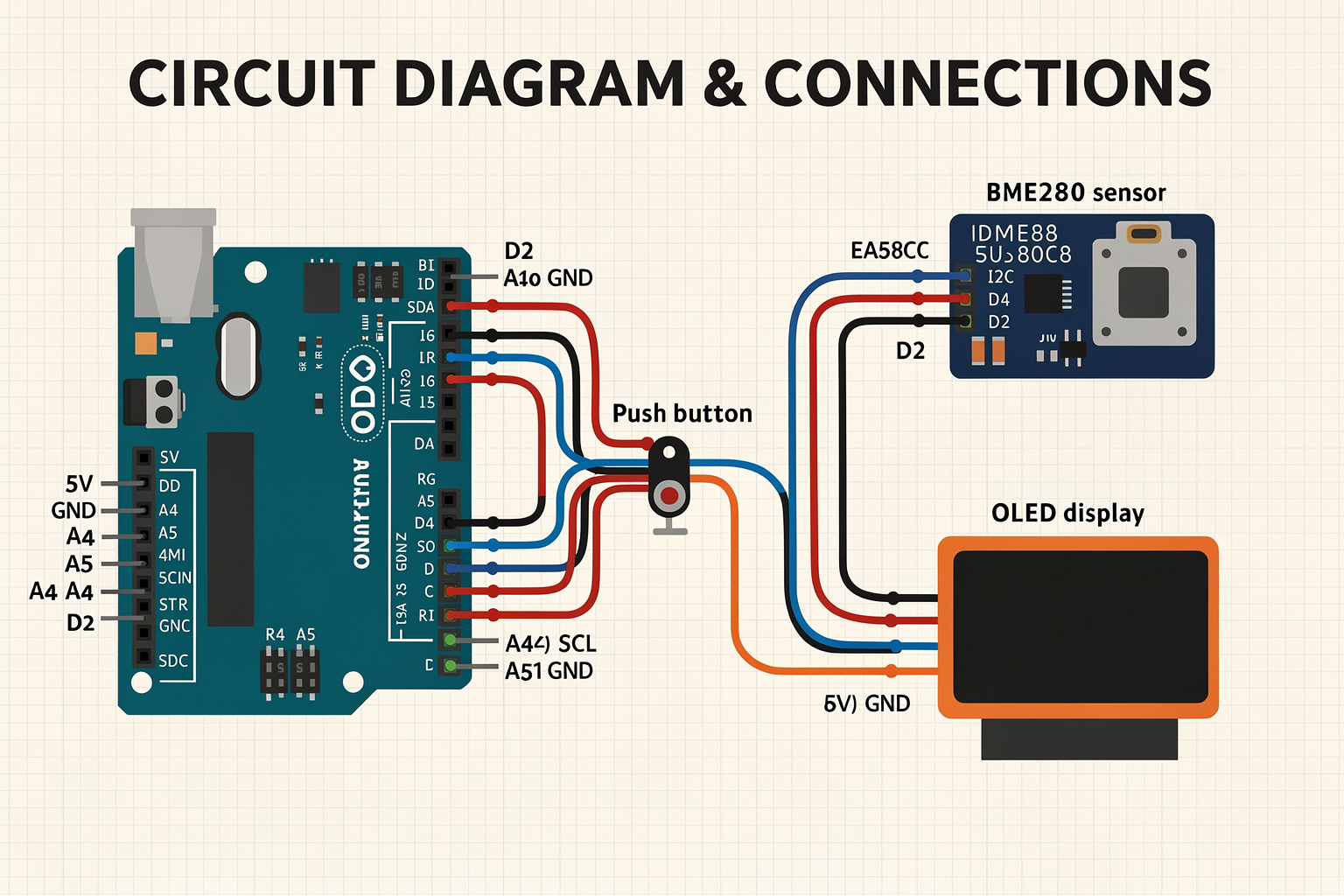
Before we start wiring, let's understand how all components connect. The beauty of this project lies in its simplicity - we're using I2C communication, which means fewer wires and easier troubleshooting.
Connection Overview:
- BME280 Sensor to Arduino: VCC, GND, SDA, SCL
- OLED Display to Arduino: VCC, GND, SDA, SCL
- Power Supply: 5V to Arduino VIN and breadboard power rails
- Push Button: Connected to digital pin 2 for manual data refresh
Detailed Pin Connections:
| Component | pin | Arduino Pin |
|---|---|---|
| BME280 VCC | +5V | 5V |
| BME280 GND | GND | GND |
| BME280 SDA | SDA | A4 |
| BME280 SCL | SCL | A5 |
| OLED VCC | +5V | 5V |
| OLED GND | GND | GND |
| OLED SDA | SDA | A4 |
| OLED SCL | SCL | A5 |
| Button Pin 1 | D2 | Digital Pin 2 |
| Button Pin 2 | GND | GND |
Common Pitfall: Many beginners accidentally connect both SDA and SCL pins incorrectly. Remember: A4 is SDA and A5 is SCL on Arduino Uno. Double-check these connections before powering up!
Step-by-Step Assembly Guide
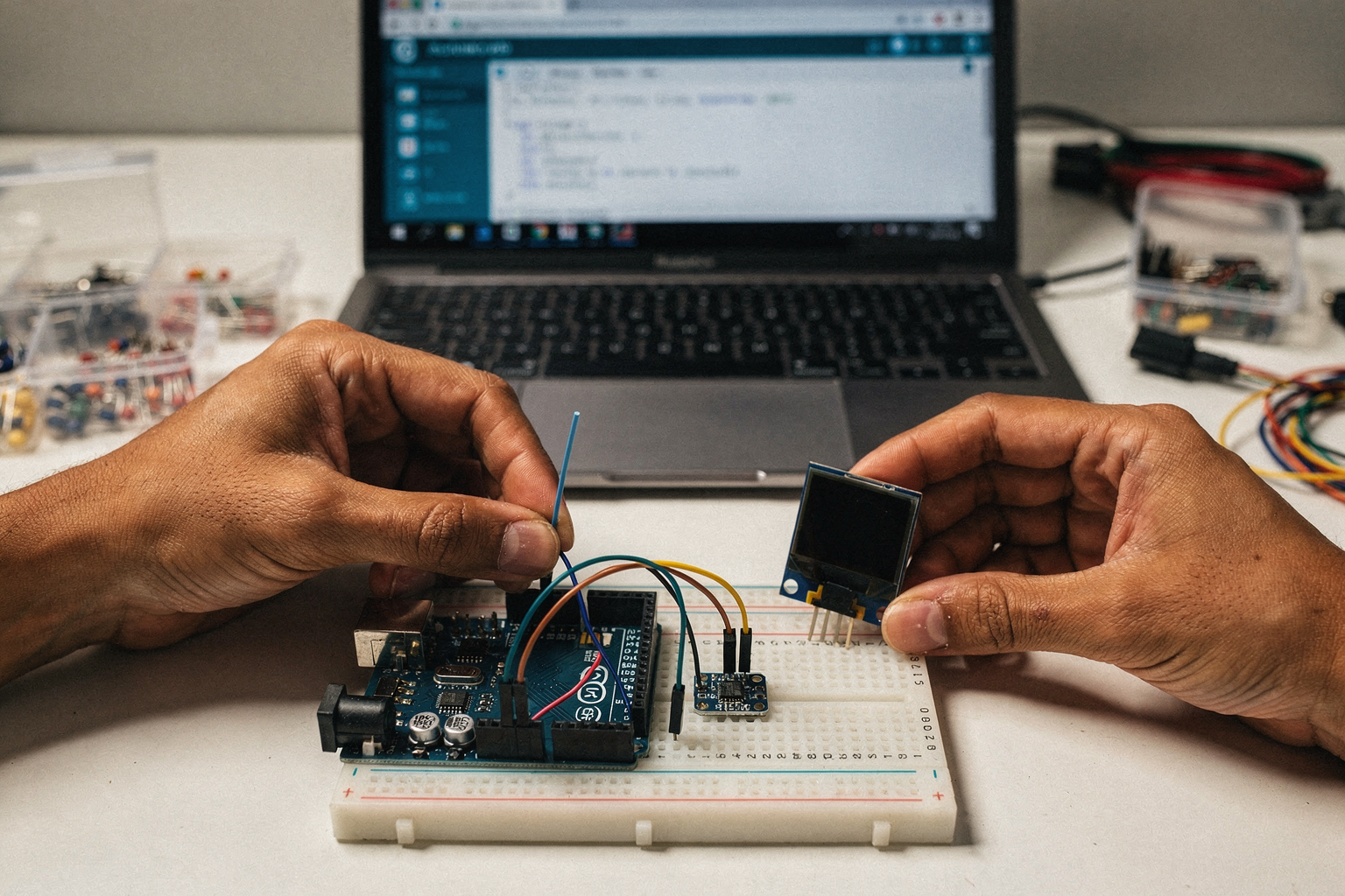
Step 1: Prepare Your Workspace
Start by setting up a clean, well-lit workspace with good organization. Keep all components within reach and use a small container to store loose jumper wires.
Step 2: Install the Breadboard
Place the breadboard on your workspace. Connect the 5V and GND power rails using jumper wires from your power supply. This is crucial for powering both the Arduino and sensors.
Step 3: Connect the Arduino
Insert the Arduino Uno into the breadboard. Connect the 5V and GND pins of the Arduino to the power rails. If you're using a USB cable, this step is already complete.
Step 4: Install the BME280 Sensor
Place the BME280 module on the breadboard. Connect the pins as follows:
- VCC to 5V rail
- GND to GND rail
- SDA to the A4 pin on Arduino
- SCL to the A5 pin on Arduino
Step 5: Install the OLED Display
Mount the OLED display on the breadboard. Connect:
- VCC to 5V rail
- GND to GND rail
- SDA to A4
- SCL to A5
Note: The OLED and BME280 share I2C pins. This is perfectly fine as they have different I2C addresses (0x76 for BME280, 0x3C for OLED).
Step 6: Connect the Push Button
Place the push button module and connect:
- One pin to digital pin 2 on Arduino
- The other pin to GND
Step 7: Final Power Check
Before applying power, double-check all connections. Now connect the power supply. The Arduino's power LED should turn on, and both sensors should initialize without any issues.
Code Explanation
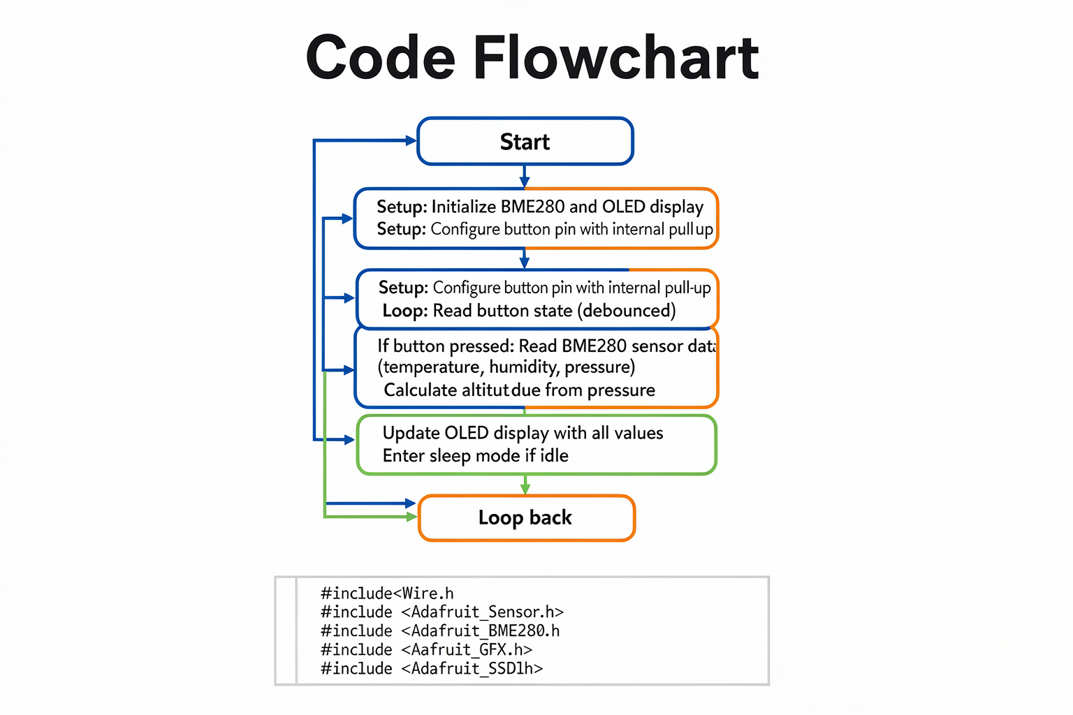
Now comes the exciting part - programming! I'll provide a complete, well-commented code that's optimized for beginners while maintaining professional standards.
Prerequisites
First, install the required libraries:
- Adafruit BME280 Library
- Adafruit Unified Sensor
- Adafruit GFX Library
- Adafruit SSD1306
You can install these through the Arduino IDE Library Manager or download them from the Adafruit website.
Complete Code Implementation
#include <Wire.h>
#include <Adafruit_BME280.h>
#include <Adafruit_GFX.h>
#include <Adafruit_SSD1306.h>
#include <avr/sleep.h>

// Initialize the BME280 sensor
Adafruit_BME280 bme;

// Initialize the OLED display
#define OLED_RESET     4
Adafruit_SSD1306 display(OLED_RESET);

// Button pin
const int buttonPin = 2;

// Variable to store button state
int buttonState = 0;
int lastButtonState = 0;
unsigned long lastDebounceTime = 0;
unsigned long debounceDelay = 50;

// Weather data variables
float temperature = 0.0;
float humidity = 0.0;
float pressure = 0.0;
float altitude = 0.0;

void setup() {
  Serial.begin(9600);

  // Initialize button pin with internal pull-up
  pinMode(buttonPin, INPUT_PULLUP);

  // Initialize OLED display
  if(!display.begin(SSD1306_SWITCHCAPVCC, 0x3C)) {
    Serial.println(F("SSD1306 allocation failed"));
    for(;;);
  }

  display.clearDisplay();
  display.setTextSize
Ready to start building?
Explore our collection of DIY kits and components. All project components mentioned in this blog are available in our store.
Browse All Projects