

Build a Line-Following Robot with Arduino and Ultrasonic Sensors
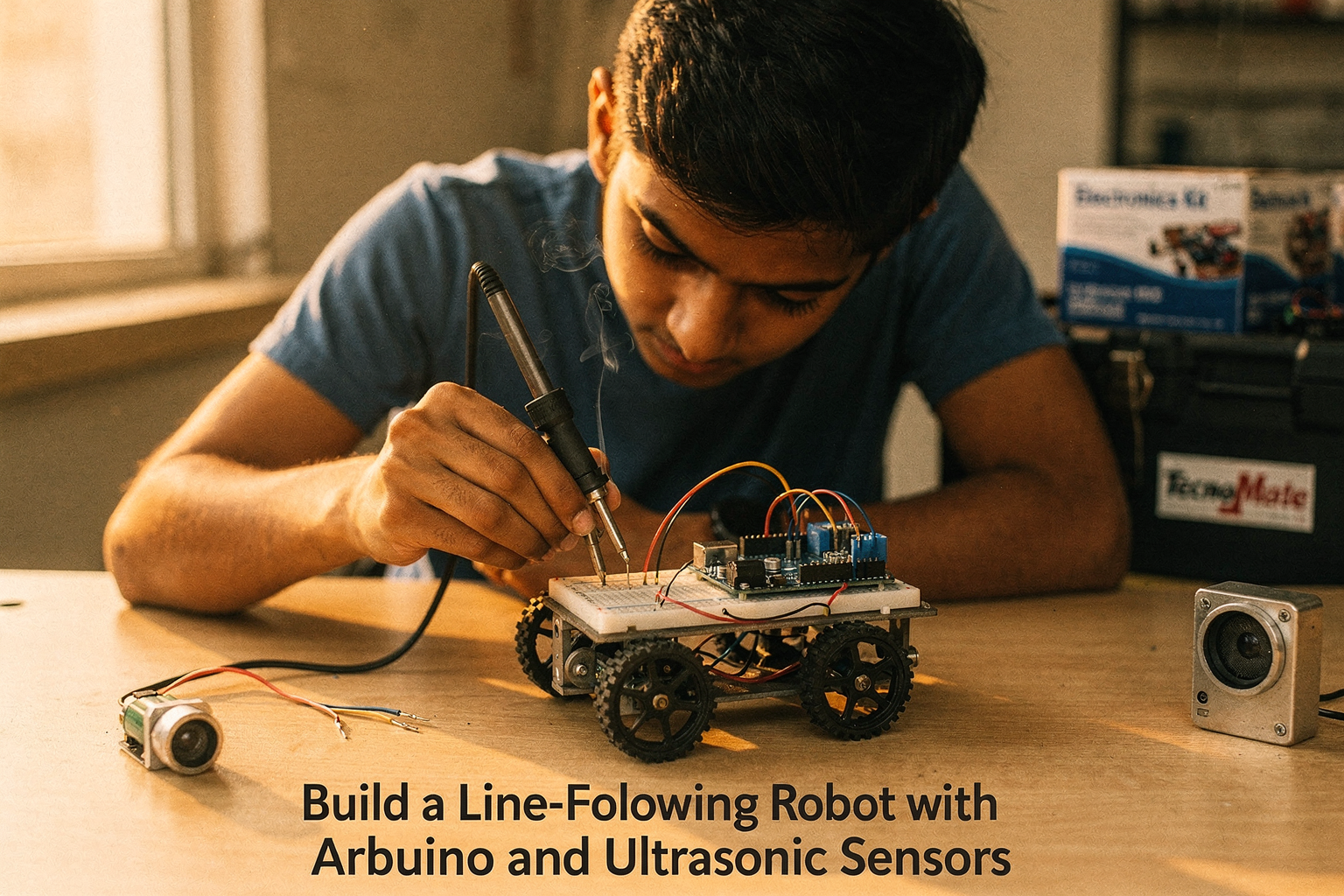
Building a line-following robot is one of the most exciting DIY projects for engineering students and electronics enthusiasts. This comprehensive guide will walk you through how to build a smart robot that can follow black lines on white surfaces using Arduino and ultrasonic sensors. As you build this robot, you'll learn essential concepts in robotics, sensors, and programming that form the foundation of modern automation systems.
Introduction: Why Build a Line-Following Robot?
Line-following robots are more than just fun projects; they're excellent learning tools that teach fundamental concepts in control systems, sensor technology, and embedded programming. When you build a line-following robot, you'll understand how real-world applications like warehouse automation systems, manufacturing robots, and even self-driving cars use sensor fusion and feedback control to navigate their environments.
This project is perfect for beginners yet challenging enough for those with some experience. As you build this robot, you'll gain hands-on experience with:
- Motor control and PWM (Pulse Width Modulation)
- Sensor calibration and data interpretation
- PID (Proportional-Integral-Derivative) control algorithms
- System integration and debugging
Understanding Line-Following Technology
Before we dive into building our robot, let's understand the core technology behind line-following robots. These robots use optical sensors to detect the contrast between the line and the surface. The robot processes this sensor data and makes real-time decisions about steering to keep it on the line.
Modern line-following robots often combine multiple sensors for better accuracy. While traditional designs use two or three IR sensors, our robot will integrate ultrasonic sensors for obstacle detection and enhanced navigation. This hybrid approach allows your robot to follow lines while avoiding obstacles—making it much more practical for real-world applications.
The control system works on a simple principle: if the sensors detect that the robot is deviating from the line, they adjust the wheel speeds accordingly. For example, if the left sensors detect the line more strongly than the right ones, the robot will turn right by reducing the left motor speed or increasing the right motor speed.
Components You'll Need (Available at TecnoMate!)
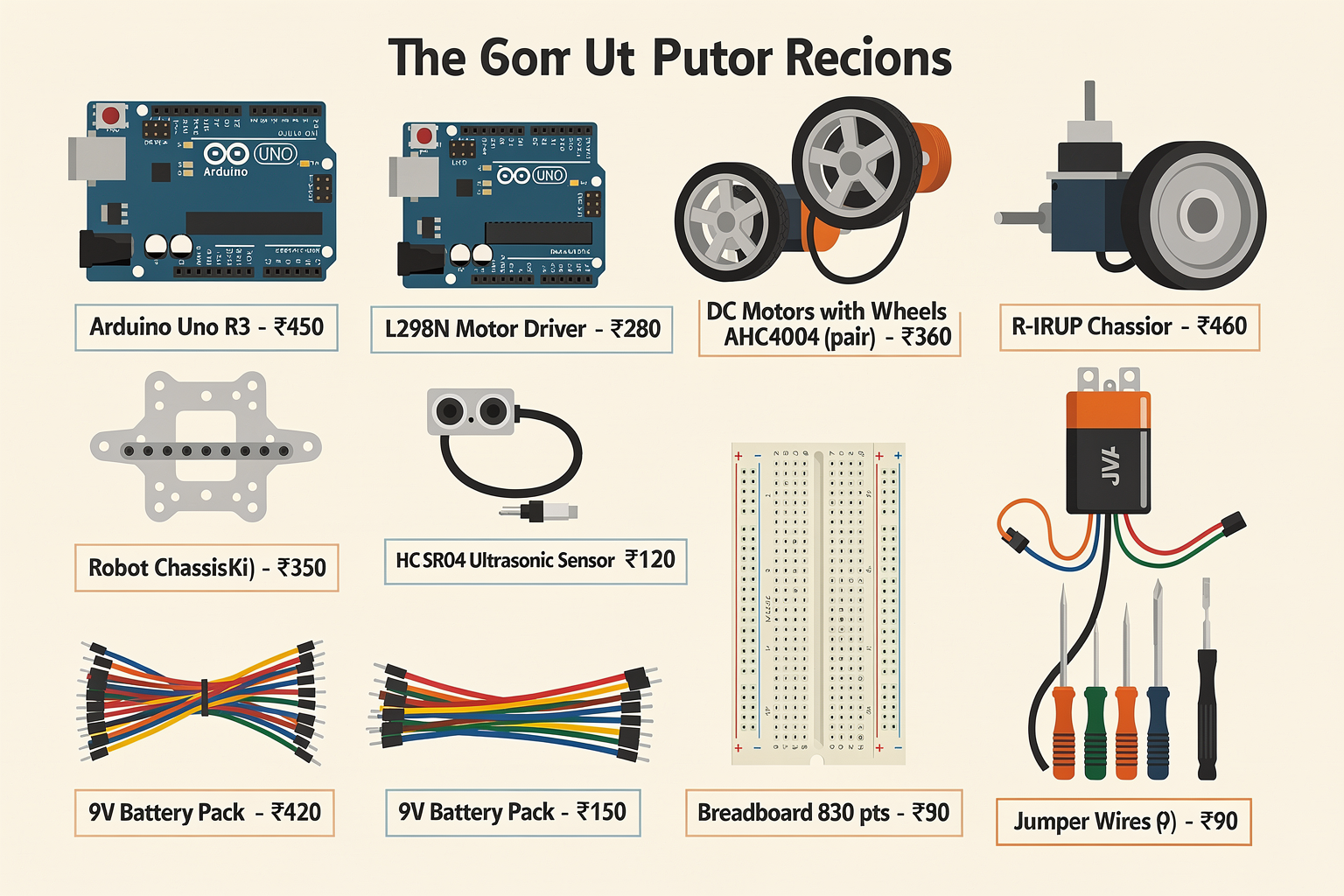
Here's a complete list of components required to build your line-following robot. All these components are readily available at TecnoMate stores across India or can be ordered online through our website.
| Component | Specification | Price (₹) | Availability at TecnoMate |
|---|---|---|---|
| Arduino Uno R3 | ATmega328P, 16MHz | 450 | ✅ All branches |
| L298N Motor Driver | Dual H-bridge | 280 | ✅ All branches |
| DC Motors with Wheels | 6V, 100RPM | 180 each | ✅ All branches |
| Ultrasonic Sensor Module | HC-SR04 | 120 | ✅ All branches |
| IR Line Following Sensor Array | 5-8 sensors | 350 | ✅ All branches |
| Chassis Kit | Plastic/Aluminium | 420 | ✅ All branches |
| Battery Pack | 9V or 6xAA | 150 | ✅ All branches |
| Breadboard | 830 points | 90 | ✅ All branches |
| Jumper Wires | 100 pieces | 80 | ✅ All branches |
| Screwdriver Set | Precision tools | 200 | ✅ All branches |
Total Cost: Approximately ₹2,300
Optional Components for Enhancement
| Component | Specification | Price (₹) |
|---|---|---|
| Servo Motor | SG90 Micro | 120 |
| LCD Display | 16x2 I2C | 180 |
| Buzzer | 5V Active | 80 |
| LED Pack | 20 pieces | 60 |
Total Optional Cost: ₹440
Circuit Diagram and Connections
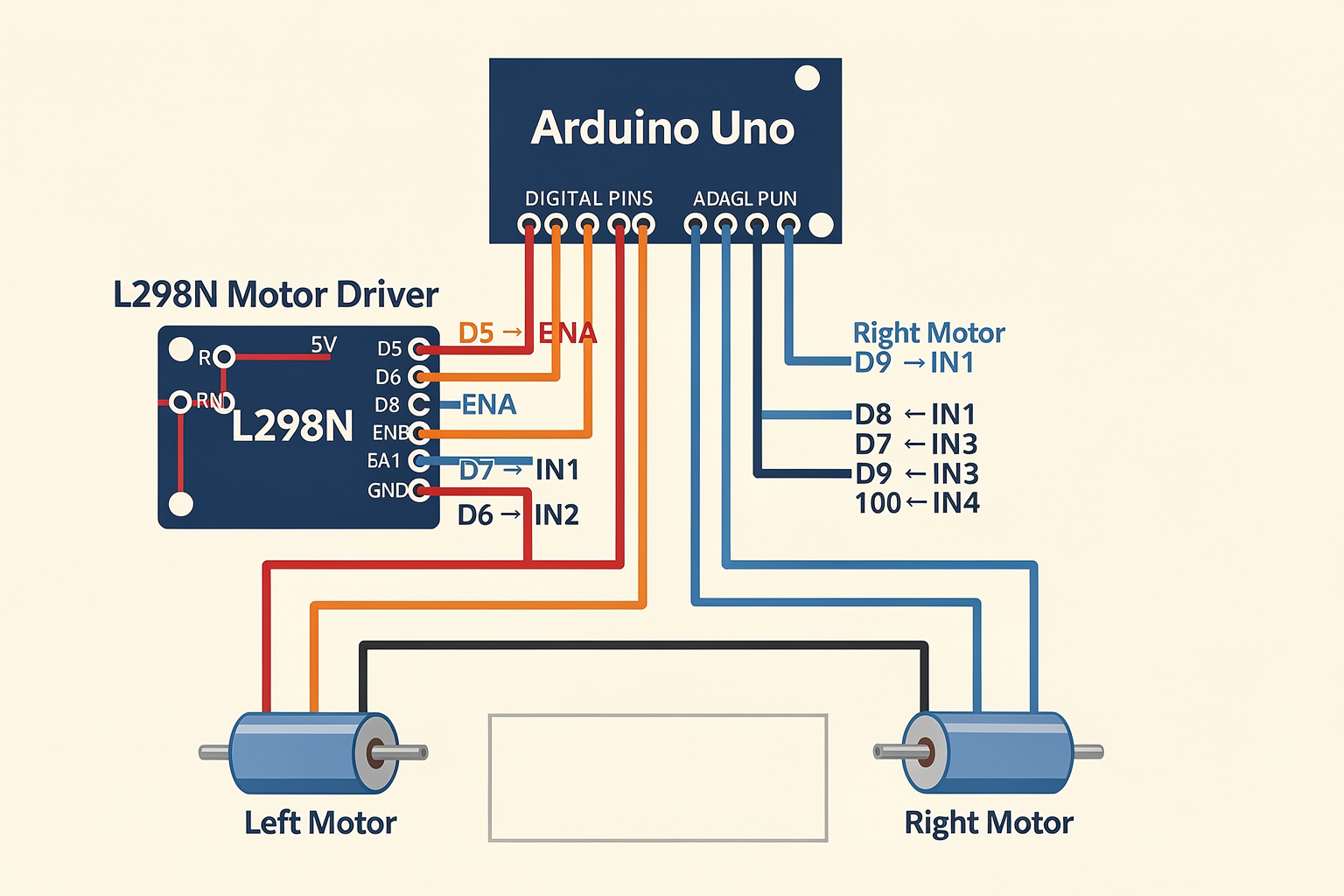
Understanding the circuit diagram is crucial before you start building. The robot consists of three main parts: the Arduino controller, the motor driver, and the sensor array.
Arduino to L298N Motor Driver Connections:
Arduino Pin 5  → ENA (Enable Left Motor)
Arduino Pin 6  → IN1 (Left Motor Direction 1)
Arduino Pin 7  → IN2 (Left Motor Direction 2)
Arduino Pin 10 → IN3 (Right Motor Direction 1)
Arduino Pin 11 → IN4 (Right Motor Direction 2)
Arduino Pin 12 → ENB (Enable Right Motor)
L298N to Motors:
- Left motor connects to OUT1 and OUT2
- Right motor connects to OUT3 and OUT4
- Both motors get 6V power from the battery pack
- L298N receives 5V from Arduino's VIN pin
Sensor Connections:
IR Line Sensors:
Sensor VCC → Arduino 5V
Sensor GND → Arduino GND
Sensor OUT → Digital pins 2-6 (depending on array size)
Ultrasonic Sensors:
VCC → Arduino 5V
GND → Arduino GND
Trig → Digital pin 8
Echo → Digital pin 9
Step-by-Step Assembly Guide
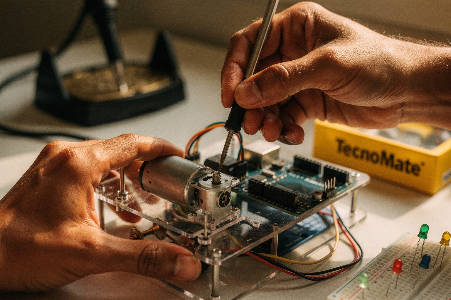
Step 1: Prepare the Chassis
Start by assembling the chassis according to the manufacturer's instructions. If you're using a kit from TecnoMate, ensure all mounting holes are properly aligned. The chassis serves as the robot's skeleton, so make sure it's sturdy and square.
Pro Tip: Use a small ruler or caliper to measure distances between mounting points for perfect alignment.
Step 2: Mount the Motors
Secure the DC motors to the chassis using the provided screws. Ensure they're parallel and at the correct distance for your wheels. Apply a small amount of thread-locking compound to prevent loosening during operation.
Common Pitfall: Don't overtighten the screws as this can crack the plastic chassis.
Step 3: Install the IR Sensor Array
Mount the IR sensor array on the front of the robot, about 1-2 cm above the ground. The sensors should be evenly spaced and angled slightly downward to detect the line effectively.
Practical Tip: Add small rubber feet under the sensor array to adjust the height easily during calibration.
Step 4: Mount the Ultrasonic Sensors
Attach the ultrasonic sensors to the front corners of the robot, angled outward at approximately 45 degrees. This setup allows the robot to detect obstacles on both sides while following the line.
Step 5: Connect the Electronics
Now it's time to wire everything according to the circuit diagram. Start with power connections first, then proceed to signal connections. Double-check all connections before powering up.
Important Safety Note: Disconnect the battery during wiring to prevent accidental motor activation.
Step 6: Upload the Code
Connect your Arduino to your computer via USB and upload the starter code. The basic code should initialize all sensors and motors, performing a quick self-test when powered on.
Arduino Programming: The Brain of Your Robot
Let's create a comprehensive program that controls our line-following robot with ultrasonic obstacle avoidance. This program combines line-following logic with real-time obstacle detection.
Basic Arduino Code
#include <NewPing.h>

// Pin definitions
#define ENA 5
#define IN1 6
#define IN2 7
#define IN3 10
#define IN4 11
#define ENB 12
#define TRIG_ULTRASONIC 8
#define ECHO_ULTRASONIC 9

// IR sensor pins (adjust based on your sensor array)
#define IR_LEFT 2
#define IR_CENTER 3
#define IR_RIGHT 4
#define IR_LEFT_RIGHT 5
#define IR_RIGHT_LEFT 6

// Ultrasonic sensor setup
#define MAX_DISTANCE 40  // Maximum distance in cm
NewPing sonar(TRIG_ULTRASONIC, ECHO_ULTRASONIC, MAX_DISTANCE);

// Motor speeds
int baseSpeed = 150;  // Base motor speed
int turnSpeed = 120;  // Speed during turns

// Variable to store obstacle distance
unsigned int uS = 0;

void setup() {
  // Initialize motor control pins
  pinMode(ENA, OUTPUT);
  pinMode(IN1, OUTPUT);
  pinMode(IN2, OUTPUT);
  pinMode(IN3, OUTPUT);
  pinMode(IN4, OUTPUT);
  pinMode(ENB, OUTPUT);

  // Initialize IR sensor pins
  pinMode(IR_LEFT, INPUT);
  pinMode(IR_CENTER, INPUT);
  pinMode(IR_LEFT_RIGHT, INPUT);
  pinMode(IR_RIGHT_LEFT, INPUT);

  // Initialize ultrasonic sensor pins
  pinMode(TRIG_ULTRASONIC, OUTPUT);
  pinMode(ECHO_ULTRASONIC, INPUT);

  Serial.begin(9600);
}

void loop() {
  // Read ultrasonic sensor for obstacle detection
  uS = sonar.ping_cm();

  // Check for obstacles
  if (uS < 20) {  // If obstacle detected within 20cm
    avoidObstacle();
  } else {
    // Normal line following
    lineFollow();
  }

  delay(50);  // Small delay for stability
}

void lineFollow() {
  // Read IR sensor values
  bool leftSensor = digitalRead(IR_LEFT);
  bool centerSensor = digitalRead(IR_CENTER);
  bool rightSensor = digitalRead(IR_RIGHT);
  bool leftRightSensor = digitalRead(IR_LEFT_RIGHT);
  bool rightLeftSensor = digitalRead(IR_RIGHT_LEFT);

  // Line following logic
  if (centerSensor && leftSensor) {
    // Move forward straight
    moveForward();
  } else if (centerSensor && rightSensor) {
    // Move forward straight (right turn detection)
    moveForward();
  } else if (leftSensor) {
    // Turn right
    turnRight();
  } else if (rightSensor) {
    // Turn left
    turnLeft();
  } else if (leftRightSensor) {
    // Sharp right turn needed
    sharpRight();
  } else if (rightLeftSensor) {
    // Sharp left turn needed
    sharpLeft();
  } else {
    // Lost the line - search pattern
    searchLine();
  }
}

void moveForward() {
  // Set motor A speed
  analogWrite(ENA, baseSpeed);
  digitalWrite(IN1, HIGH);
  digitalWrite(IN2, LOW);

  // Set motor B speed
  analogWrite(ENB, baseSpeed);
  digitalWrite(IN3, HIGH);
  digitalWrite(IN4, LOW);
}

void turnRight() {
  // Set motor A speed
  analogWrite(ENA, turnSpeed);
  digitalWrite(IN1, HIGH);
  digitalWrite(IN2, LOW);

  // Set motor B speed
  analogWrite(ENB, baseSpeed);
  digitalWrite(IN3, HIGH);
  digitalWrite(IN4, LOW);
}

void turnLeft() {
  // Set motor A speed
  analogWrite(ENA, baseSpeed);
  digitalWrite(IN1, HIGH);
  digitalWrite(IN2, LOW);

  // Set motor B speed
  analogWrite(ENB, turnSpeed);
  digitalWrite(IN3, HIGH);
  digitalWrite(IN4, LOW);
}

void sharpRight() {
  // Set motor A speed
  analogWrite(ENA, 100);
  digitalWrite(IN1, HIGH);
  digitalWrite(IN2, LOW);

  // Set motor B speed
  analogWrite(ENB, 80);
  digitalWrite(IN3, HIGH);
  digitalWrite(IN4, LOW);
}

void sharpLeft() {
  // Set motor A speed
  analogWrite(ENA, 80);
  digitalWrite(IN1, HIGH);
  digitalWrite(IN2, LOW);

  // Set motor B speed
  analogWrite(ENB, 100);
  digitalWrite(IN3, HIGH);
  digitalWrite(IN4, LOW);
}

void avoidObstacle() {
  // Stop motors
  stopMotors();

  // Back up
  delay(500);
  backUp();
  delay(500);

  // Turn around
  turnAround();

  // Move forward again
  delay(300);
  moveForward();
}

void stopMotors() {
  analogWrite(ENA, 0);
  analogWrite(ENB, 0);
  digitalWrite(IN1, LOW);
  digitalWrite(IN2, LOW);
  digitalWrite(IN3, LOW);
  digitalWrite(IN4, LOW);
}

void backUp() {
  // Set motor A reverse
  analogWrite(ENA, baseSpeed);
  digitalWrite(IN1, LOW);
  digitalWrite(IN2, HIGH);

  // Set motor B reverse
  analogWrite(ENB, baseSpeed);
  digitalWrite(IN3, LOW);
  digitalWrite(IN4, HIGH);
}

void turnAround() {
  // Turn left to complete 180-degree turn
  analogWrite(ENA, baseSpeed);
  digitalWrite(IN1, HIGH);
  digitalWrite(IN2, LOW);

  analogWrite(ENB, baseSpeed);
  digitalWrite(IN3, LOW);
  digitalWrite(IN4, HIGH);
}

void searchLine() {
  // Simple search pattern: turn right, left, right
  stopMotors();
  delay(300);

  // Turn right
  digitalWrite(IN1, HIGH);
  digitalWrite(IN2, LOW);
  digitalWrite(IN3, LOW);
  digitalWrite(IN4, HIGH);
  analogWrite(ENA, 80);
  analogWrite(ENB, 80);
  delay(1000);

  // Turn left
  stopMotors();
  delay(300);

  digitalWrite(IN1, HIGH);
  digitalWrite(IN2, LOW);
  digitalWrite(IN3, LOW);
  digitalWrite(IN4, HIGH);
  analogWrite(ENA, 80);
  analogWrite(ENB, 80);
  delay(1000);

  // Turn right again
  stopMotors();
  delay(300);
}
Code Explanation
The code above implements a sophisticated line-following algorithm with obstacle avoidance. Here's a breakdown of the key components:
1. Sensor Reading and Initialization:
- The program initializes both IR sensors for line detection and ultrasonic sensors for obstacle detection
- Ultrasonic sensors use the NewPing library for reliable distance measurement
- IR sensors are configured as digital inputs for binary line detection
2. Main Loop Logic: The main loop continuously checks for obstacles before deciding whether to follow the line or avoid an obstacle. This priority-based approach ensures the robot never crashes into obstacles.
3. Line Following Algorithm: The line-following logic uses multiple sensor readings to determine the robot's position relative to the line:
- Center sensor active: Robot is on the line
- Left sensor active: Robot needs to turn right
- Right sensor active: Robot needs to turn left
- Corner sensors active: Sharp turns required
- No sensors active: Robot has lost the line and initiates search pattern
4. Motor Control Functions: Each movement function (moveForward, turnRight, etc.) sets the appropriate motor directions and speeds using PWM for variable speed control.
5. Obstacle Avoidance: When an obstacle is detected within 20cm, the robot stops, backs up, turns around, and continues forward. This simple but effective strategy ensures safe navigation in cluttered environments.
Calibration and Testing
After assembling and programming your robot, calibration is essential for optimal performance.
Sensor Calibration Steps:
- IR Sensor Calibration:
- Place the robot on a test track with a clear black line on a white
Ready to start building?
Explore our collection of DIY kits and components. All project components mentioned in this blog are available in our store.
Browse All Projects