

Building a Custom Mechanical Keyboard with Arduino Pro Micro
Introduction
Building your own custom mechanical keyboard is an exciting project that combines electronics, programming, and mechanical design. As engineering students in India, you'll find this project not only enhances your technical skills but also gives you a keyboard perfectly tailored to your typing preferences. The feeling of typing on a keyboard you built yourself is unmatched, and with Arduino Pro Micro, you have a powerful yet affordable microcontroller at your disposal.
This comprehensive guide will walk you through every step of building a custom 60% mechanical keyboard. We'll cover everything from component selection to programming, with a focus on practical implementation using components readily available in the Indian market. Let's dive into the world of custom mechanical keyboards!
Components Required
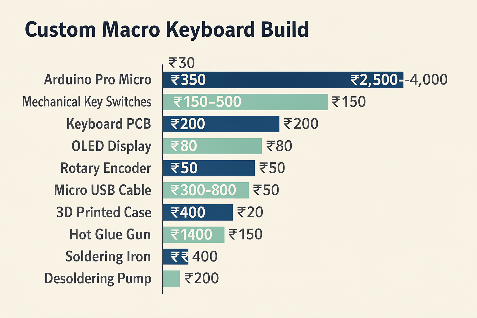
Before we start building, let's gather all the necessary components. Here's a detailed breakdown of what you'll need for your custom mechanical keyboard project:
| Component | Specification | Price (₹) | Supplier/Availability |
|---|---|---|---|
| Arduino Pro Micro | ATmega32U4, 5V, USB-capable | 350 | Available at TechNiche, Robu.in |
| Mechanical Key Switches | Cherry MX compatible, 60% layout | 2,500-4,000 | Available at Keychron India, MechBoards |
| Keyboard PCB | Perforated protoboard or custom PCB | 150-500 | Available at Robu.in, PCB Power |
| OLED Display | 0.96" I2C SSD1306 | 200 | Available at TechNiche, Robu.in |
| Rotary Encoder | With push button | 120 | Available at Robu.in, Amazon India |
| USB-C Cable | 1.2m, data transfer capable | 80 | Available at Croma, Reliance Digital |
| Micro USB Cable | For programming | 50 | Available at any electronics store |
| 3D Printed Case | Optional | 300-800 | Available at 3DPrintIndia, MakerGhat |
| Hot Glue Gun | For securing switches | 250 | Available at hardware stores |
| Soldering Iron | 40W with tips | 400 | Available at Robu.in, Amazon India |
| Solder Wire | 60/40 rosin core | 150 | Available at Robu.in, electronics markets |
| Desoldering Pump | For corrections | 200 | Available at Robu.in, electronics markets |
Total Estimated Cost: ₹5,800 - ₹9,250 (excluding 3D printed case)
Understanding the Basics
Before diving into the building process, let's understand the fundamental concepts of custom mechanical keyboards:
How Mechanical Keyboards Work
Unlike membrane keyboards that use rubber domes, mechanical keyboards use individual mechanical switches for each key. These switches provide tactile feedback and have a longer lifespan (typically 50-100 million keystrokes). The Arduino Pro Micro will handle the key scanning and USB communication, while the keyboard PCB routes the signals to the microcontroller.
Why Arduino Pro Micro?
The Arduino Pro Micro is ideal for custom keyboard projects due to:
- Native USB capability for direct HID (Human Interface Device) communication
- ATmega32U4 processor with sufficient memory for keymaps
- Small form factor perfect for keyboard builds
- Affordable price point (₹350)
- USB-C support for programming and power
Keyboard Layout Options
For this guide, we'll focus on a 60% layout, which includes:
- Alphabetic keys (QWERTY)
- Navigation cluster (Home, End, Delete, etc.)
- Function row
- Arrow keys
- Number row
- Dedicated volume controls
- Programmable layers for additional functionality
Circuit Design and Setup
Understanding the Key Matrix
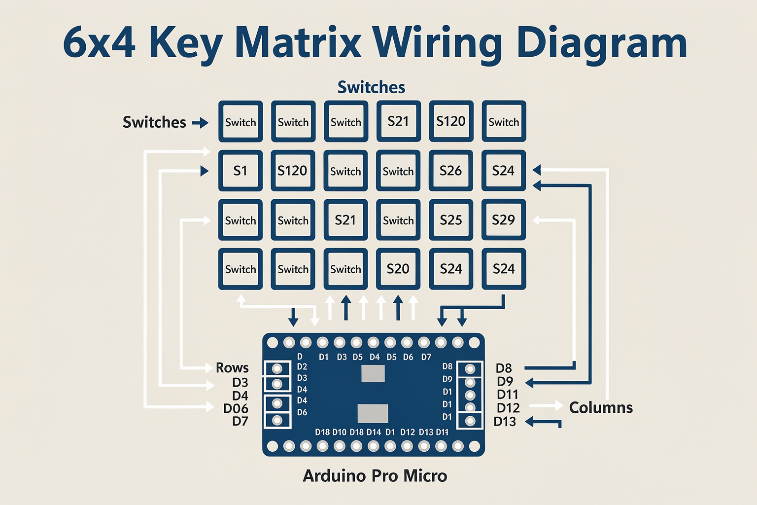
A mechanical keyboard uses a matrix layout where switches share rows and columns. This reduces the number of I/O pins required. For a 60% keyboard, we need approximately 24 keys, which translates to a 6×4 matrix (6 rows, 4 columns).
PCB Selection and Preparation
For beginners, I recommend using a perforated protoboard initially. Here's how to prepare it:
- Mark a 6×4 grid on the PCB
- Drill holes at switch positions (use 5mm drill bit)
- Insert mechanical switches at each position
- Solder the pins to the PCB
Wiring the Matrix
Here's how to connect the switches to the Arduino Pro Micro:
Row Pins (to Arduino)
R1 → D2
R2 → D3
R3 → D4
R4 → D5
R5 → D6
R6 → D7

Column Pins (to Arduino)
C1 → D8
C2 → D9
C3 → D10
C4 → D11
Adding Extra Features
OLED Display Integration
Connect the OLED display using I2C:
- SDA → A4
- SCL → A5
- VCC → 5V
- GND → GND
Rotary Encoder
Connect the rotary encoder to simulate media controls:
- Pin A → D12
- Pin B → D13
- Pin GND → GND
Step-by-Step Building Guide
Step 1: PCB Preparation
- Cut your PCB to size (approximately 100mm × 60mm)
- Mark a 6×4 grid with 19mm spacing (standard for Cherry MX switches)
- Use a 5mm drill bit to create mounting holes
- Clean the PCB surface with isopropyl alcohol
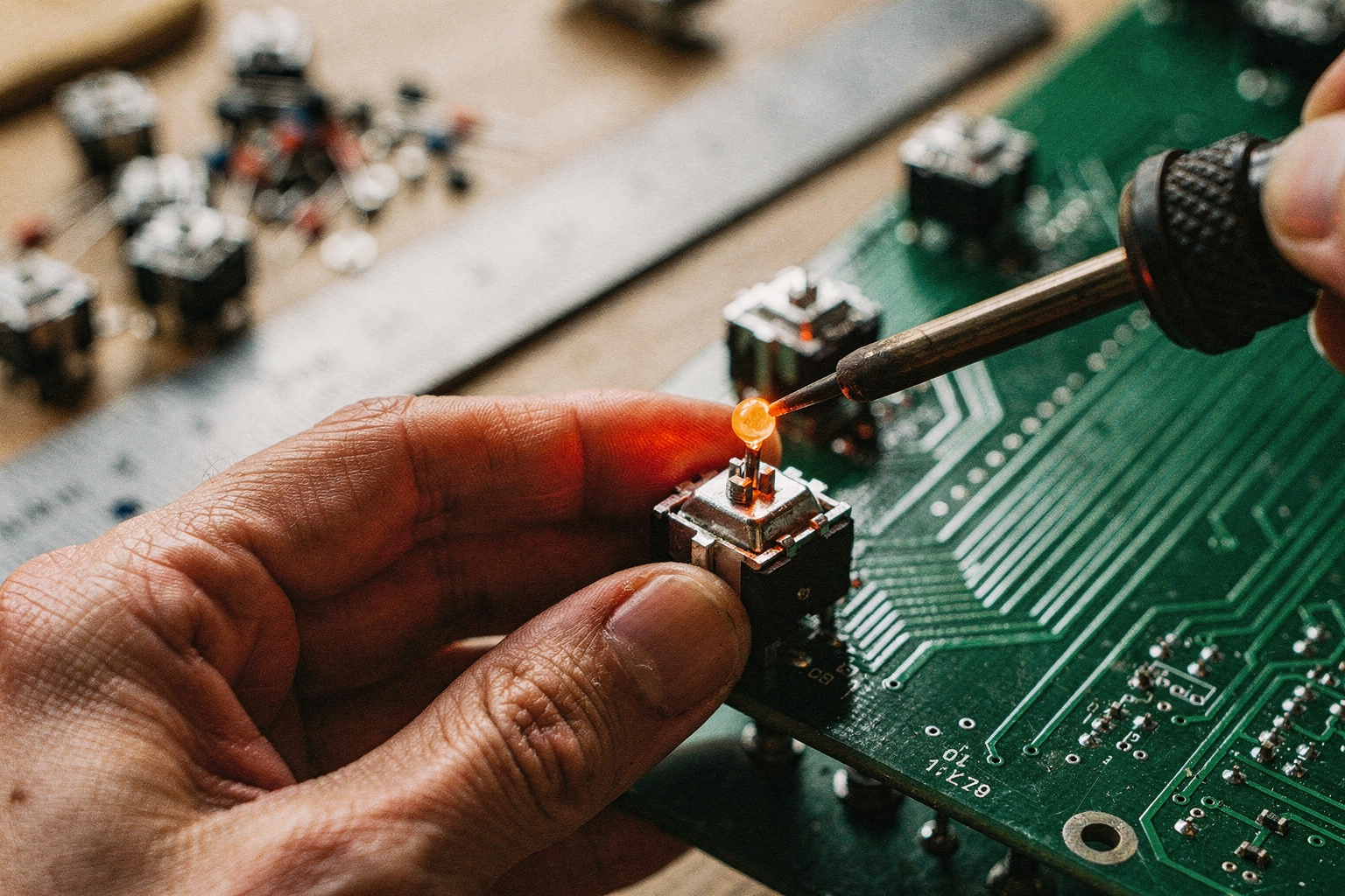
Step 2: Switch Installation
- Insert switches into the PCB at marked positions
- Ensure switches are oriented correctly (top facing up)
- Bend the pins slightly to secure switches
- Solder each pin to the PCB using a soldering iron
Step 3: Pro Micro Mounting
- Mark mounting holes on your keyboard case or base
- Use standoffs to mount the Pro Micro
- Ensure USB port is accessible for programming
Step 4: Row and Column Wiring
- Solder jumper wires from each row pin to the corresponding Arduino pins
- Solder jumper wires from each column pin to the Arduino pins
- Double-check all connections before powering on
Step 5: Component Assembly
- Mount the OLED display on the case
- Install the rotary encoder
- Route cables neatly to avoid interference
- Secure all components with hot glue or screws
Step 6: Testing Before Final Assembly
- Connect the Pro Micro to your computer via USB
- Upload the basic test code (we'll cover this next)
- Test each key individually
- Verify OLED display functionality
- Test rotary encoder movements
Code Implementation
Now let's write the code to bring your keyboard to life. Here's a comprehensive Arduino sketch with syntax highlighting:
#include <Keyboard.h>
#include <Wire.h>
#include <Adafruit_GFX.h>
#include <Adafruit_SSD1306.h>

// OLED Display configuration
#define OLED_RESET -1
Adafruit_SSD1306 display(128, 64, &Wire, OLED_RESET);

// Pin definitions for row and column matrix
const uint8_t ROWS = 6;
const uint8_t COLS = 4;
const uint8_t rowPins[ROWS] = {2, 3, 4, 5, 6, 7};
const uint8_t colPins[COLS] = {8, 9, 10, 11};

// Rotary encoder pins
const uint8_t encoderPinA = 12;
const uint8_t encoderPinB = 13;
const uint8_t encoderButton = 14;

// Keymap for 60% layout
const uint8_t keys[ROWS][COLS] = {
  // Row 0 (Function layer)
  {0, 0, 0, 0},
  // Row 1
  {'1', '2', '3', '4'},
  // Row 2 (Home row - Left hand)
  {'q', 'w', 'e', 'r'},
  // Row 3 (Home row - Right hand)
  {'t', 'y', 'u', 'i'},
  // Row 4 (Bottom row - Left hand)
  {'z', 'x', 'c', 'v'},
  // Row 5 (Bottom row - Right hand)
  {'a', 's', 'd', 'f'}
};

// Layer management
int currentLayer = 0;

// Rotary encoder variables
int lastEncoderState = 0;
int volumeLevel = 0;

void setup() {
  // Initialize keyboard
  Keyboard.begin();

  // Initialize OLED display
  if(!display.begin(SSD1306_SWITCHCAPVCC, 0x3C)) {
    // OLED initialization failed
    while(1);
  }

  // Set all pins as inputs with pullups
  for(uint8_t i = 0; i < ROWS; i++) {
    pinMode(rowPins[i], INPUT_PULLUP);
  }

  for(uint8_t i = 0; i < COLS; i++) {
    pinMode(colPins[i], INPUT_PULLUP);
  }

  // Set encoder pins
  pinMode(encoderPinA, INPUT_PULLUP);
  pinMode(encoderPinB, INPUT_PULLUP);
  pinMode(encoderButton, INPUT_PULLUP);

  // Initialize display
  display.clearDisplay();
  display.setTextSize(1);
  display.setTextColor(WHITE);
  display.setCursor(0, 0);
  display.println("Keyboard Ready!");
  display.display();

  delay(2000);
  display.clearDisplay();
}

void loop() {
  checkKeyboard();
  checkEncoder();
  updateDisplay();
}

void checkKeyboard() {
  for(uint8_t row = 0; row < ROWS; row++) {
    // Set all column pins to OUTPUT and HIGH (inactive)
    for(uint8_t col = 0; col < COLS; col++) {
      pinMode(colPins[col], OUTPUT);
      digitalWrite(colPins[col], HIGH);
    }

    // Set current row to INPUT (active low)
    pinMode(rowPins[row], INPUT_PULLUP);

    // Check all columns in this row
    for(uint8_t col = 0; col < COLS; col++) {
      if(digitalRead(colPins[col]) == LOW) {
        // Key pressed at (row, col)
        pressKey(row, col);
        break; // Debounce
      }
    }
  }
}

void pressKey(uint8_t row, uint8_t col) {
  if(row < ROWS && col < COLS) {
    uint8_t key = keys[row][col];
    if(key != 0) {
      Keyboard.press(key);
      delay(10); // Small delay to register press
      Keyboard.release(key);
    }
  }
}

void checkEncoder() {
  int currentState = (digitalRead(encoderPinA) << 1) | digitalRead(encoderPinB);

  // Check for button press
  if(digitalRead(encoderButton) == LOW) {
    delay(50); // Debounce
    Keyboard.press(KEY_MEDIA_PLAY_PAUSE);
    delay(50);
    Keyboard.release(KEY_MEDIA_PLAY_PAUSE);
  }

  // Check for rotation
  if(currentState != lastEncoderState) {
    if((currentState == 0b01 && lastEncoderState == 0b00) ||
       (currentState == 0b10 && lastEncoderState == 0b00) ||
       (currentState == 0b00 && lastEncoderState == 0b01) ||
       (currentState == 0b00 && lastEncoderState == 0b10)) {

      // Determine rotation direction
      if(currentState == 0b01 && lastEncoderState == 0b00) {
        volumeLevel = (volumeLevel + 1) % 100;
      } else if(currentState == 0b10 && lastEncoderState == 0b00) {
        volumeLevel = (volumeLevel - 1 + 100) % 100;
      }
    }

    lastEncoderState = currentState;
  }
}

void updateDisplay() {
  display.clearDisplay();
  display.setTextSize(1);
  display.setCursor(0, 0);
  display.println("Custom KB");
  display.println("Layer: " + String(currentLayer));
  display.println("Vol: " + String(volumeLevel) + "%");
  display.println("Encoder: OK");
  display.display();
}
Key Features Explained:
- Matrix Scanning: The code uses a row-column scanning technique to detect key presses efficiently
- Layer Support: Easy to add additional layers for more keys
- OLED Display: Shows current layer, volume level, and status
- Rotary Encoder: Controls volume and can simulate media controls
- USB HID: Native USB communication without additional drivers
Testing and Calibration
Basic Functionality Testing
After uploading the code, test each aspect:
- Individual Key Testing: Press each key to ensure it registers correctly
- OLED Display: Verify all sections of the display work
- Rotary Encoder: Test both rotation and button functions
- USB Connection: Ensure the keyboard is recognized by your computer
Calibration Steps
- Key Debounce: If keys register multiple times, increase the delay in
pressKey()function - Matrix Issues: If some keys don't work, check the corresponding row and column connections
- OLED Problems: Verify I2C connections and address (0x3C by default)
- Encoder Sensitivity: Adjust the delay in encoder detection if needed
Advanced Testing
For comprehensive testing, write a test sketch that:
- Logs keypresses to Serial Monitor
- Tests each key individually
- Measures response time
- Verifies simultaneous key presses (n-key rollover)
Troubleshooting
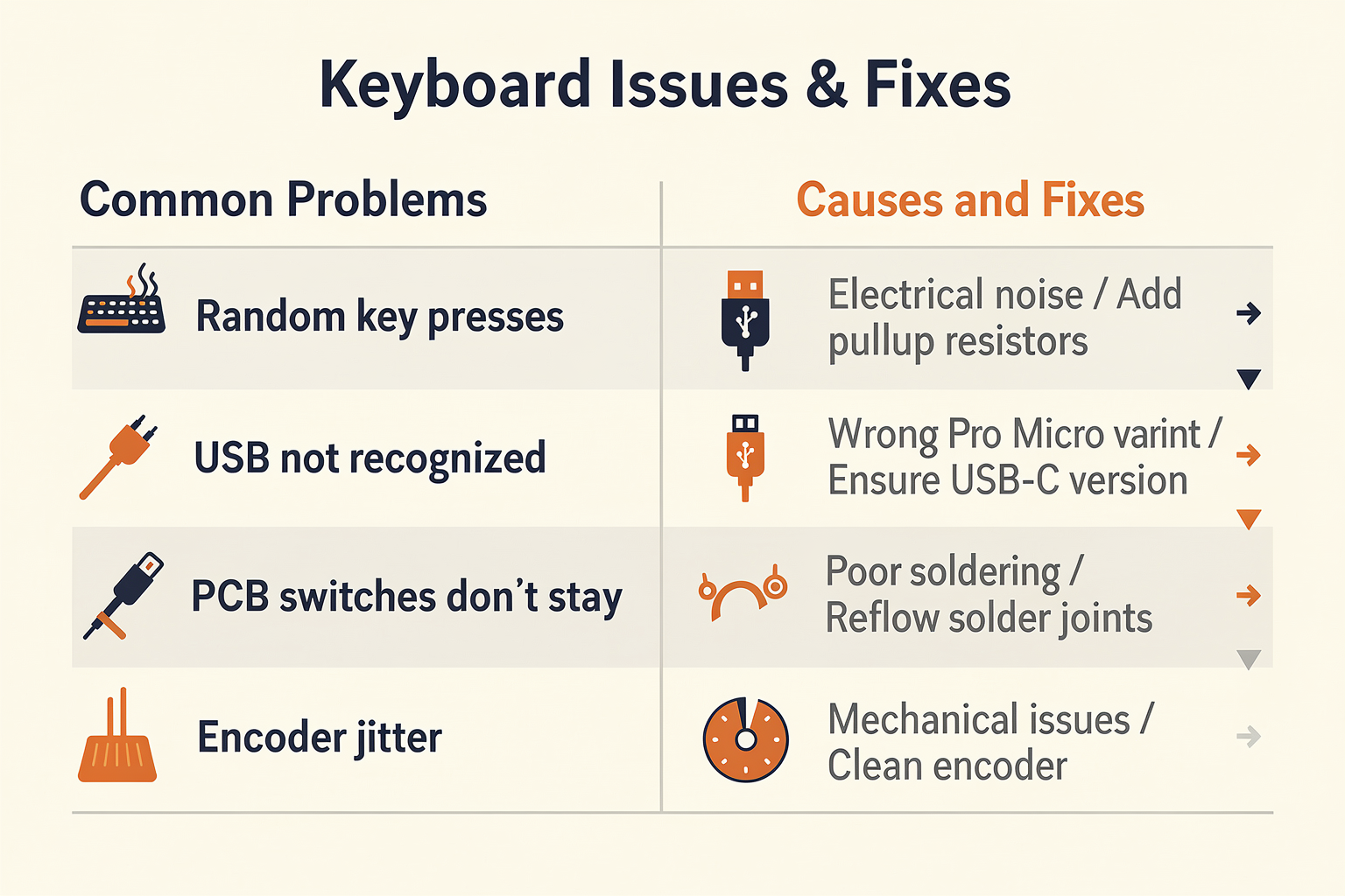
Even with careful assembly, you might encounter some issues. Here's a comprehensive troubleshooting guide:
| Problem | Possible Cause | Solution |
|---|---|---|
| No keys register | Wrong wiring | Check row/column connections |
| Keys register wrong | Incorrect keymap | Verify keys[][] array |
| OLED doesn't display | I2C issues | Check SDA/SCL connections |
| Encoder doesn't work | Wrong pin assignment | Verify encoderPinA/B/Button pins |
| Random key presses | Electrical noise | Add pullup resistors or check grounding |
| Slow response | Matrix scanning too slow | Optimize loop timing |
| USB not recognized | Wrong Pro Micro variant | Ensure you're using USB-C compatible version |
| PCB switches don't stay | Poor soldering | Reflow solder joints |
| Encoder jitter | Mechanical issues | Clean encoder or replace if damaged |
| Keys stick down | Switch debris | Clean switches with isopropyl alcohol |
Common Pitfalls to Avoid
- Mixing up rows and columns: Double-check your wiring diagram
- Forgetting pullup resistors: Use INPUT_PULLUP when possible
- Ignoring USB power requirements: Use a powered USB hub if needed
- Not testing before final assembly: Always test functionality first
- Poor case design: Ensure adequate ventilation and cable management
Frequently Asked Questions
Frequently Asked Questions
Q: What programming language should I use for custom keyboard firmware? A: For Arduino-based keyboards, you'll primarily use Arduino IDE with C/C++. The provided code uses the standard Arduino library, making it accessible for
Ready to start building?
Explore our collection of DIY kits and components. All project components mentioned in this blog are available in our store.
Browse All Projects