

Building a LoRa-based Long Range Communication System for Remote Sensors
Introduction: Why LoRa-based Long Range Communication Systems Matter
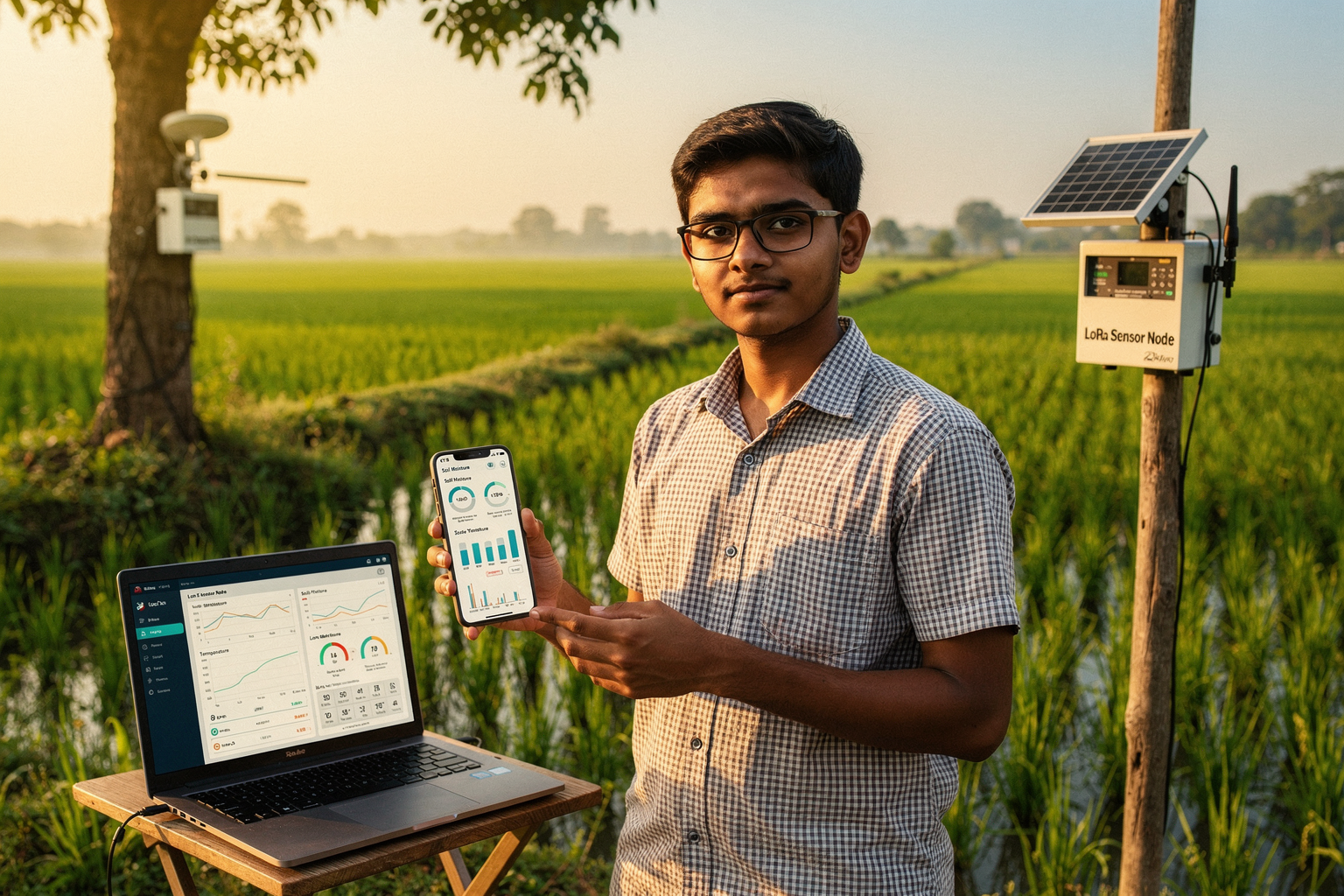
In today's interconnected world, remote sensing applications are revolutionizing industries from agriculture to environmental monitoring. Imagine monitoring soil moisture in a 10-acre farm across 5 kilometers, tracking wildlife in remote forests, or managing smart city infrastructure without worrying about WiFi dead zones. This is where LoRa (Long Range) technology comes into play, offering wireless communication capabilities that span several kilometers while consuming minimal power.
Building a LoRa-based system isn't just about connecting devices—it's about creating networks that bridge geographical gaps, reduce infrastructure costs, and enable data collection from the most inaccessible locations. For Indian engineering students and DIY enthusiasts, mastering LoRa technology opens doors to numerous research opportunities and practical applications tailored to India's diverse landscape, from Himalayan research stations to agricultural fields in Punjab.
Components Required for Your LoRa System
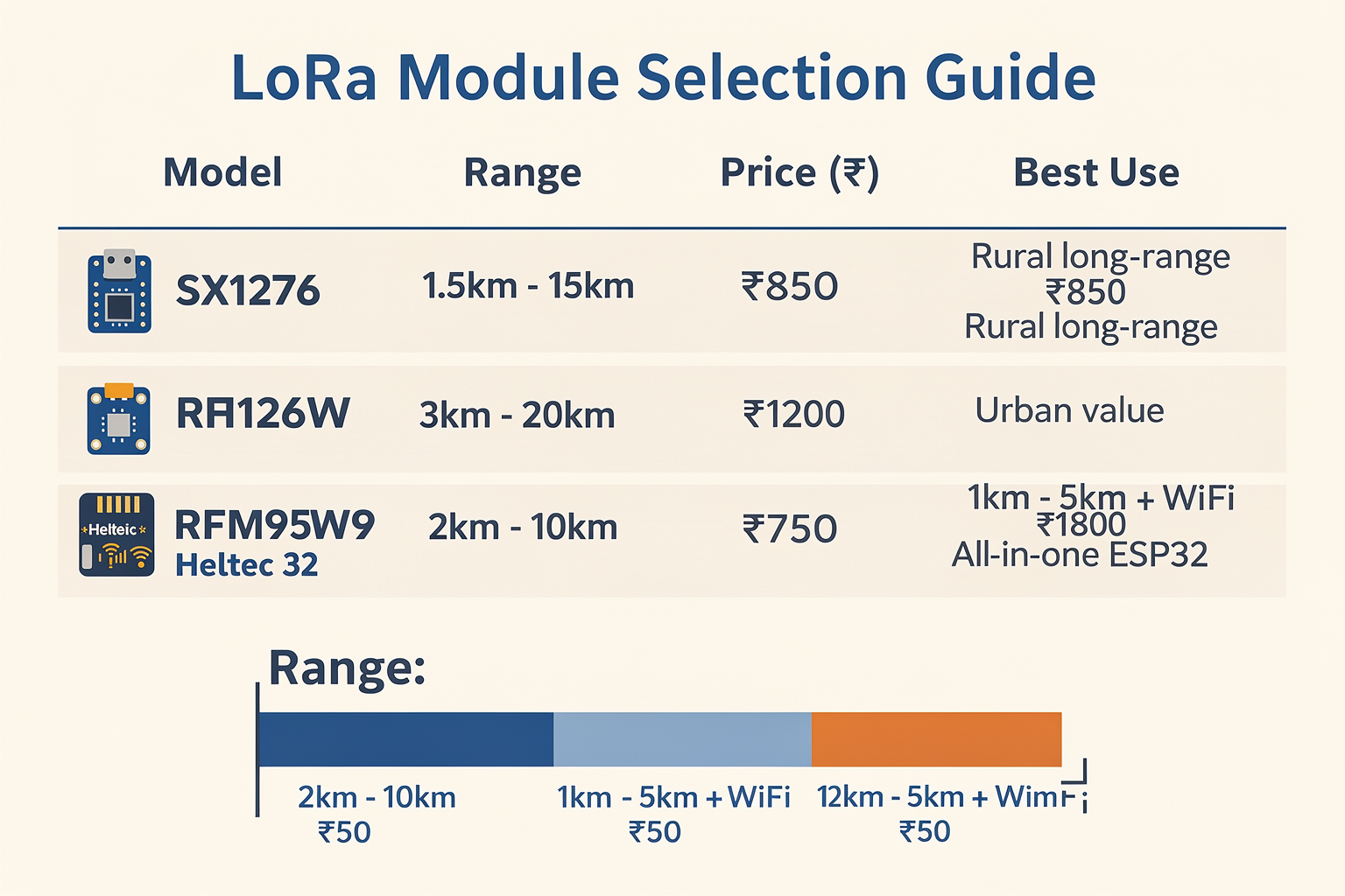
Let's break down the essential components you'll need. TecnoMate offers most of these items at competitive prices across India:
LoRa Module Selection
| Component | Specification | Price (₹) | Availability |
|---|---|---|---|
| SX1276 LoRa Module | 1.5km - 15km range | 850 | In Stock |
| SX1262 LoRa Module | 3km - 20km range | 1200 | In Stock |
| RFM95W LoRa Module | 2km - 10km range | 750 | In Stock |
| Heltec LoRa 32 | Built-in LoRa + ESP32 | 1800 | In Stock |
The choice between modules depends on your range requirements and budget. For urban environments, the RFM95W offers excellent value. For longer ranges in rural areas, the SX1276 or SX1262 provides better performance.
Microcontroller and Development Board
| Component | Specification | Price (₹) | Features |
|---|---|---|---|
| ESP32 Dev Kit | WiFi + BT + LoRa | 950 | Multiple GPIO pins |
| Arduino Nano | 16MHz, ATmega328P | 350 | USB powered |
| Raspberry Pi Pico | 133MHz, RP2040 | 250 | MicroPython support |
| ST Nucleo L476RG | ARM Cortex-M4 | 1200 | Professional development |
For educational purposes, the ESP32 Dev Kit with built-in LoRa is ideal as it simplifies the building process while providing WiFi connectivity for data logging.
Power Supply Solutions
| Component | Specification | Price (₹) | Battery Life |
|---|---|---|---|
| 3.7V Li-Po Battery | 500mAh | 150 | 2-3 days |
| Solar Panel Module | 6V, 100mA | 450 | Continuous |
| Power Bank 10000mAh | USB output | 800 | 1 week+ |
| Battery Charger Module | Li-Po charging | 200 | Fast charging |
Solar-powered systems are perfect for agricultural applications and can be easily sourced from solar vendors in Delhi or online platforms like Amazon India.
Antennas and RF Accessories
| Component | Specification | Price (₹) | Range Impact |
|---|---|---|---|
| Dipole Antenna 433MHz | 2dBi | 120 | 50% increase |
| PCB Antenna 868MHz | 2dBi | 150 | 30% increase |
| Directional Yagi Antenna | 9dBi | 850 | 300% increase |
| RF Connector SMA | Gold plated | 25 | Better connectivity |
Antenna placement significantly impacts your long-range communication. For maximum range, consider mounting directional antennas at elevated positions.
Circuit Diagram and Hardware Setup
Basic Circuit Configuration
        LoRa Module (RFM95W)
        ┌─────────────────┐
        │                 │
Arduino  │ VCC ------------> 3.3V
        │ GND ------------> GND
        │ DIO0 ------------> Arduino Pin 2
        │ DIO1 ------------> Arduino Pin 3
        └─────────────────┘
Step-by-Step Hardware Assembly
- Breadboard Setup: Place your ESP32 or Arduino on the breadboard with adequate spacing for the LoRa module.
- Power Connections: Connect the 3.3V and GND pins of the LoRa module to your microcontroller's power pins.
- SPI Communication:
- Connect MISO (Pin 50)
- Connect MOSI (Pin 23)
- Connect SCK (Pin 18)
- Connect NSS/SS (Pin 15)
- DIO Pins: Connect DIO0 and DIO1 to interrupt pins on your microcontroller.
Pro Tip: Use 22AWG jumper wires for reliable connections. Avoid using breadboards with poor power distribution—consider using a protoboard with proper power rails for stable operation.
Software and Firmware Setup
Arduino IDE Configuration
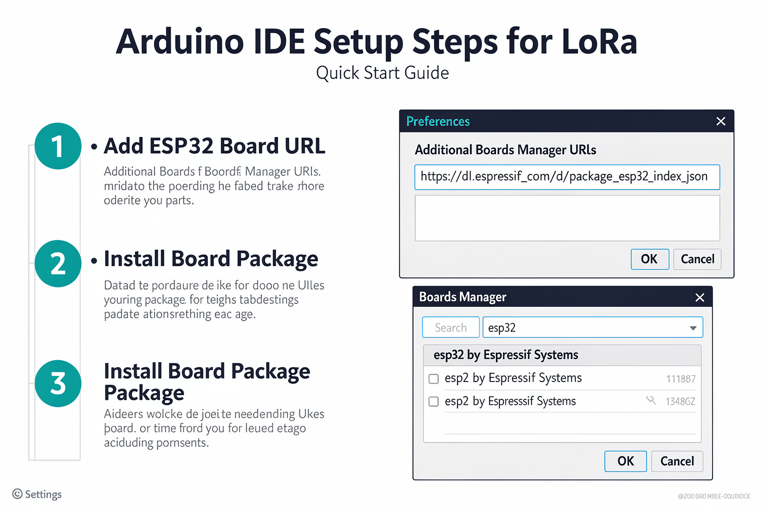
- Install Arduino IDE: Download from Arduino's official website or use the Arduino App for mobile development.
- Add ESP32 Board Manager: Go to File > Preferences and add
http://espressif.com/git/espboards.gitto Additional Board Manager URLs. - Install ESP32 Boards: Go to Tools > Board > Boards Manager and search for "ESP32".
LoRa Library Installation
// Open Arduino IDE and go to Sketch > Include Library > Manage Libraries
// Search for "MCCI LoRaWAN LMIC Library" or "LoRa by Sandeep Mistry"
Code Implementation: Building the Transmitter
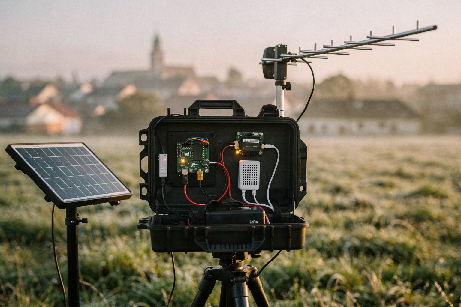
Here's a complete example for a temperature and humidity sensor transmitter:
#include <LoRa.h>
#include <DHT.h>
#include <DHT_U.h>

#define RFM95_CS 10
#define DHTPIN 4
#define DHTTYPE DHT22
#define LED_BUILTIN 2

LoRaWANClass Lora;
DHT dht(DHTPIN, DHTTYPE);

void setup() {
  Serial.begin(115200);
  pinMode(LED_BUILTIN, OUTPUT);
  dht.begin();

  // Configure LoRa module
  LoRa.setPins(RFM95_CS);
  if (!LoRa.begin(915E6)) {
    Serial.println("LoRa init failed");
    while(1);
  }

  Serial.println("LoRa initialized successfully");
}

void loop() {
  float humidity = dht.readHumidity();
  float temperature = dht.readTemperature();

  if (isnan(humidity) || isnan(temperature)) {
    Serial.println("Failed to read from DHT sensor!");
    delay(2000);
    return;
  }

  // Prepare data packet
  String data = String(temperature, 2) + "," + String(humidity, 2);

  // Send data via LoRa
  LoRa.beginPacket();
Ready to start building?
Explore our collection of DIY kits and components. All project components mentioned in this blog are available in our store.
Browse All Projects