

Introduction
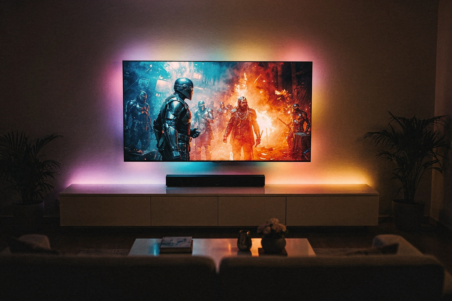
Have you ever watched a movie on your TV and wished the colors spilled beyond the screen, creating an immersive viewing experience? This is exactly what Ambilight technology does! Originally developed by Philips, Ambilight projects colored light onto the wall behind your television, matching what's happening on screen. The result is a more engaging, cinematic experience right in your living room.
But why spend hundreds of thousands on commercial Ambilight systems when you can build your own? With the rising popularity of WS2812B LEDs (also known as NeoPixels) and affordable microcontrollers, creating a DIY Ambilight system has never been easier or more affordable. In this comprehensive guide, we'll walk you through building your own high-quality Ambilight system using components readily available in India.
This DIY project is perfect for engineering students looking to enhance their practical skills while creating something genuinely useful. The WS2812B LEDs we'll use are individually addressable RGB LEDs that can produce millions of colors, making them ideal for Ambilight applications. Let's dive in and create your very own Ambilight system!
Components Required
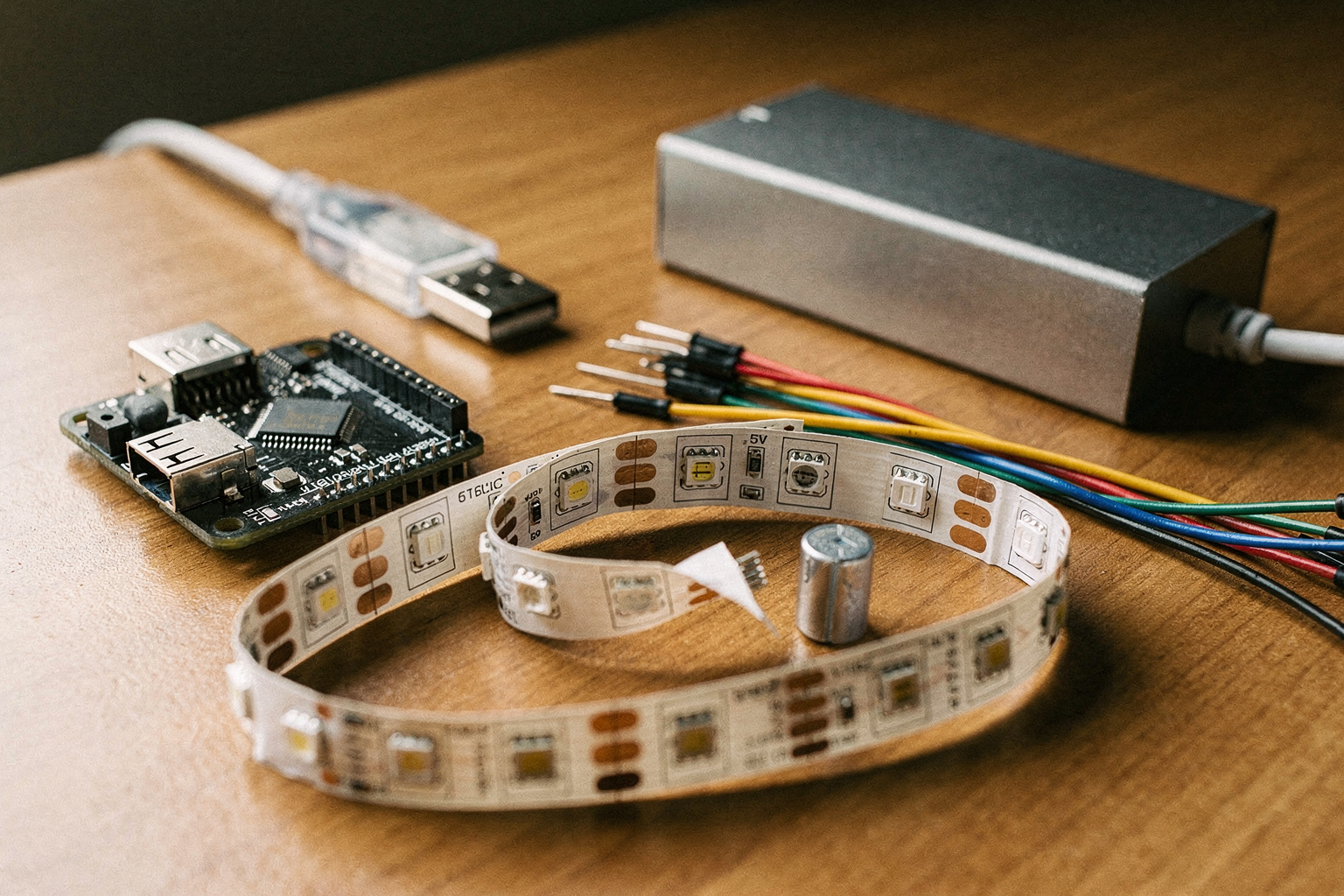
| Component | Specification | Price (₹) | Availability |
|---|---|---|---|
| WS2812B LED Strip | 5M, 60 LEDs/m | 1,200 | Available on Amazon India, SparkFun India |
| ESP32 Dev Board | WiFi + Bluetooth | 450 | Amazon India, Robu.in, MakerHuts |
| 5V 10A Power Supply | 50W Regulated | 800 | Local electronics shops, Amazon |
| USB to TTL Adapter | CP2102/CH340G | 150 | Amazon, Robu.in |
| Aluminum Profile (50mm) | 5M Length | 600 | Hardware stores, Amazon |
| Diffuser Acrylic | 25mm x 500mm | 250 | Local plastic suppliers |
| Capacitors | 1000µF 25V | 30 | Lamington Road, Amazon |
| Resistors | 220Ω, 10kΩ | 10 | Lamington Road, online stores |
| Jumper Wires | 40-pin | 80 | Amazon, Robu.in |
Understanding WS2812B LEDs
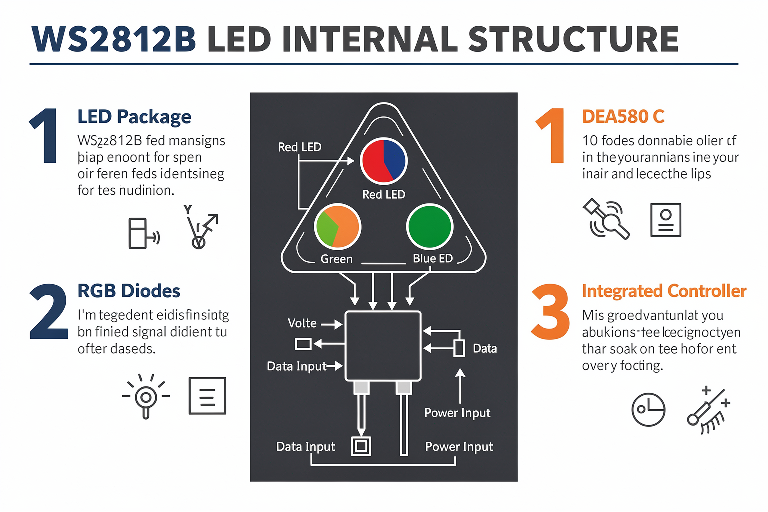
The WS2812B is a remarkable component that combines three LEDs (Red, Green, Blue) and a controller chip in a single package. Each LED can be individually controlled and dimmed, allowing for an impressive range of colors and effects. When connected in sequence, they form a chain where each LED's data output connects to the next LED's data input.
What makes WS2812B special for Ambilight applications? Here's why they're perfect:
- Individual Addressability: Each LED can display a different color
- Integrated Controller: No need for external shift registers
- Built-in Constant Current: Ensures consistent brightness across all LEDs
- Low Voltage Operation: 5V power supply is safe and readily available
- Self-Healing: If one LED fails, the rest continue to work
Technical Note: WS2812B LEDs require precise timing signals to function correctly. The ESP32's high-speed GPIO pins are perfect for generating these signals, making it the ideal microcontroller for this project.
Circuit Design and Setup
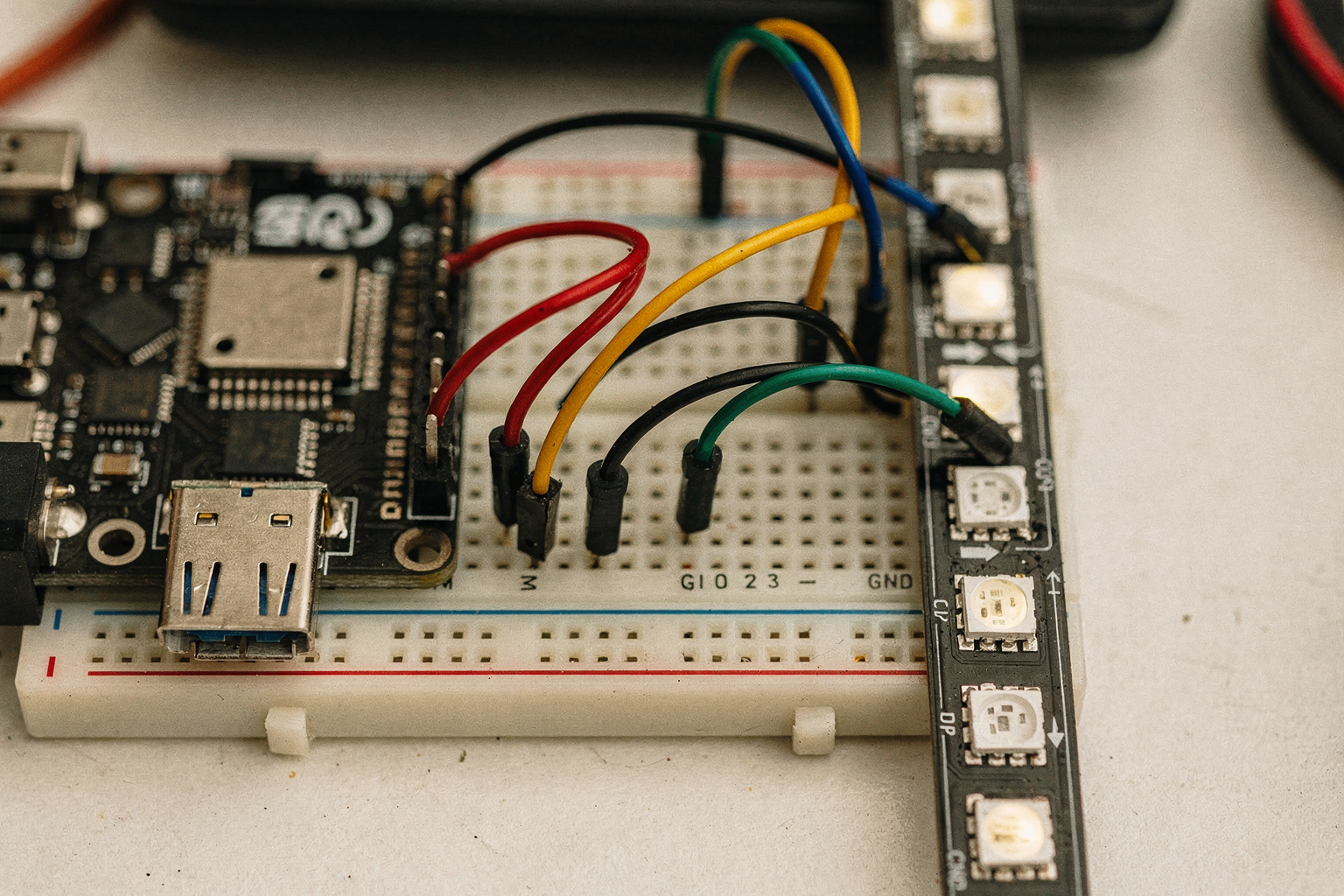
Circuit Diagram
[Power Supply] --> [Capacitor] --> [ESP32 5V]
                              |
                              V
                        [Ground]
                              |
[ESP32 Data Pin (GPIO 23)] --> [WS2812B Strip]
                              |
                              V
                        [Ground] <-- [Power Supply GND]
Wiring Instructions
-
Power Connection: Connect the 5V output from your power supply to the ESP32's VIN pin through a 1000µF capacitor to smooth out voltage fluctuations.
-
Data Connection: Connect GPIO pin 23 of the ESP32 to the data input of the WS2812B strip. Use a 300Ω resistor in series with this connection to prevent signal damage.
-
Ground Connection: Ensure all grounds are properly connected - ESP32 GND, power supply GND, and WS2812B strip GND.
-
Power to LEDs: Power the WS2812B strip directly from the 5V power supply, NOT from the ESP32. The ESP32 can only supply about 500mA, while your 5M strip might need more.
Pro Tip: Place the capacitor as close as possible to the ESP32's power pins to minimize noise in the power supply.
Step-by-Step Implementation Guide
Step 1: Physical Installation
-
Mount the LED Strip: Attach the WS2812B strip to the aluminum profile using the adhesive backing. The aluminum acts as a heat sink to keep the LEDs cool.
-
Install the Diffuser: Place the acrylic diffuser in front of the LED strip. This creates an even, soft light that's pleasant to the eyes.
-
Position Behind TV: Mount the setup on the wall behind your TV at approximately eye level when seated.
Step 2: Software Setup
-
Install ESP32 Board Support: Open Arduino IDE and add ESP32 board support through File > Preferences > Additional Boards Manager URLs.
-
Install Required Libraries: Install the following libraries through the Library Manager:
- Adafruit NeoPixel
- ArduinoJson
-
Configure Board: Select your board (e.g., "ESP32 Dev Module") and the correct COM port.
Step 3: Connection to TV
We need to capture what's happening on your TV screen. Here are two approaches:
Method 1: HDMI Capture Card
- Connect an HDMI capture card to your TV's HDMI out
- Connect the capture card to your ESP32
- Use the HDMI signal to extract RGB values
Method 2: Simple Color Detection
- Point a small webcam at your TV screen
- Process the video to extract dominant colors
For this DIY project, we'll focus on Method 2 as it's more cost-effective (webcam costs only ₹300-500).
Step 4: Programming the ESP32
Now let's write the code to capture colors from the TV and display them on our LED strip. Here's the complete program:
#include <Adafruit_NeoPixel.h>
#include <ArduinoJson.h>
#include <WiFi.h>
#include <HTTPClient.h>
#include <ArduinoOTA.h>

#define LED_PIN 23
#define LED_COUNT 300 // 5M strip with 60 LEDs/m
#define BUTTON_PIN 0

Adafruit_NeoPixel strip(LED_COUNT, LED_PIN, NEO_GRB + NEO_KHZ800);

// TV-related variables
const char* ssid = "YourWiFiSSID";
const char* password = "YourWiFiPassword";
const char* server_url = "http://your-server-url.com/get_colors";

// Color smoothing variables
long last_update = 0;
int smooth_factor = 5; // Lower = more responsive, higher = smoother
int current_r = 0, current_g = 0, current_b = 0;
int target_r = 0, target_g = 0, target_b = 0;

void setup() {
  Serial.begin(115200);

  // Initialize NeoPixel strip
  strip.begin();
  strip.setBrightness(50); // Adjust brightness as needed
  strip.show();

  // Initialize button
  pinMode(BUTTON_PIN, INPUT_PULLUP);

  // Setup WiFi
  WiFi.begin(ssid, password);
  while (WiFi.status() != WL_CONNECTED) {
    delay(500);
    Serial.print(".");
  }
  Serial.println("\nWiFi connected!");

  // Setup OTA updates
  ArduinoOTA.setHostname("Ambilight-ESP32");
  ArduinoOTA.setPassword("yourpassword");
  ArduinoOTA.begin();

  // Initial display
  setColor(0, 0, 0);
}

void loop() {
  ArduinoOTA.handle();

  // Handle button press
  if (digitalRead(BUTTON_PIN) == LOW) {
    delay(50); // Debounce
    setColor(0, 0, 0); // Turn off on button press
    while (digitalRead(BUTTON_PIN) == LOW); // Wait for release
  }

  // Capture colors from TV every 50ms
  unsigned long current_time = millis();
  if (current_time - last_update > 50) {
    last_update = current_time;
    captureColorsFromTV();
  }

  // Smooth transition
  smoothColors();
  displayColors();
}

void captureColorsFromTV() {
  if (WiFi.status() == WL_CONNECTED) {
    HTTPClient http;
    http.begin(server_url);

    int httpCode = http.GET();
    if (httpCode > 0) {
      String payload = http.getString();

      // Parse JSON response
      DynamicJsonDocument doc(1024);
      deserializeJson(doc, payload);

      target_r = doc["r"] | 0;
      target_g = doc["g"] | 0;
      target_b = doc["b"] | 0;

      Serial.printf("Captured - RGB: %d, %d, %d\n", target_r, target_g, target_b);
    }

    http.end();
  }
}

void smoothColors() {
  // Smooth transitions for less flickering
  current_r += (target_r - current_r) / smooth_factor;
  current_g += (target_g - current_g) / smooth_factor;
  current_b += (target_b - current_b) / smooth_factor;
}

void setColor(int r, int g, int b) {
  target_r = r;
  target_g = g;
  target_b = b;
}

void displayColors() {
  for (int i = 0; i < LED_COUNT; i++) {
    // Create gradient effect
    int pixel_r = current_r;
    int pixel_g = current_g;
    int pixel_b = current_b;

    // Add some variation for more interesting effects
    if (i > 0) {
      pixel_r = constrain(pixel_r + random(-20, 20), 0, 255);
      pixel_g = constrain(pixel_g + random(-20, 20), 0, 255);
      pixel_b = constrain(pixel_b + random(-20, 20), 0, 255);
    }

    strip.setPixelColor(i, strip.Color(pixel_r, pixel_g, pixel_b));
  }

  strip.show();
}
Step 5: Setting Up the Color Capture Server
You'll need a simple server to process the webcam feed and send color data to the ESP32. Here's a Python script using OpenCV:
import cv2
import numpy as np
import json
from http.server import BaseHTTPRequestHandler
from socketserver import HTTPServer
import threading

class ColorCaptureServer(BaseHTTPRequestHandler):
    def do_GET(self):
        # Capture frame from webcam
        ret, frame = cap.read()

        if ret:
            # Convert to HSV for better color detection
            hsv = cv2.cvtColor(frame, cv2.COLOR_BGR2HSV)

            # Define range for white/gray
            lower_white = np.array([0, 0, 200])
            upper_white = np.array([180, 30, 255])
            mask = cv2.inRange(hsv, lower_white, upper_white)

            # Find largest white area (assumed to be TV screen)
            contours, _ = cv2.findContours(mask, cv2.RETR_EXTERNAL, cv2.CHAIN_APPROX_SIMPLE)
            largest_contour = max(contours, key=cv2.contourArea)

            # Get average color in the largest white area
            x, y, w, h = cv2.boundingRect(largest_contour)
            tv_region = frame[y:y+h, x:x+w]
            avg_color = np.mean(tv_region, axis=(0, 1))

            # Convert RGB to 0-255 range
            rgb = [int(avg_color[2]), int(avg_color[1]), int(avg_color[0])]

            # Send response
            self.send_response(200)
            self.send_header('Content-type', 'application/json')
            self.end_headers()
            response = json.dumps({"r": rgb[0], "g": rgb[1], "b": rgb[2]})
            self.wfile.write(response.encode())
        else:
            self.send_response(400)
            self.end_headers()

def run_server():
    server = HTTPServer(('0.0.0.0', 8080), ColorCaptureServer)
    print("Server running on port 8080...")
    server.serve_forever()

# Initialize webcam
cap = cv2.VideoCapture(0)
if not cap.isOpened():
    print("Error: Could not open webcam")
    exit()

# Run server in separate thread
threading.Thread(target=run_server).start()

# Keep main thread alive
try:
    while True:
        pass
except KeyboardInterrupt:
    cap.release()
    cv2.destroyAllWindows()
Customization Options
Different Display Modes
Your Ambilight system can display more than just TV content. Here are some interesting modes:
Mode 1: Music Visualizer
void musicVisualizer() {
  for (int i = 0; i < LED_COUNT; i++) {
    int pixel = (i * 100) % 100;
    int brightness = abs(pixel - musicData) % 100;
    strip.setPixelColor(i, strip.Color(brightness, brightness/2, brightness/4));
  }
}
Mode 2: Breathing Effect
void breathingEffect(int r, int g, int b) {
  static int phase = 0;
  phase += 2;

  if (phase > 180) phase = 0;

  int intensity = map(phase, 0, 180, 0, 255);
  strip.setPixelColor(0, strip.Color(r*intensity/255, g*intensity/255, b*intensity/255));
}
Color Palettes
Predefined color schemes can enhance different types of content:
void applyMovieNightPalette() {
  setColor(80, 60, 100);
}

void applyGamingPalette() {
  setColor(120, 60, 180);
}

void applyRelaxingPalette() {
  setColor(100, 150, 1
Ready to start building?
Explore our collection of DIY kits and components. All project components mentioned in this blog are available in our store.
Browse All Projects