

DIY Oscilloscope Using Arduino and Python for Signal Analysis
Introduction
Creating your own oscilloscope is an exciting DIY project that every engineering student should experience. Not only does it save you thousands of rupees compared to commercial oscilloscopes, but it also gives you a deep understanding of how oscilloscopes work. In this comprehensive guide, we'll walk you through building a DIY oscilloscope using Arduino and Python that can capture and analyze signals with reasonable accuracy.
This DIY oscilloscope project is perfect for measuring voltage signals, debugging circuits, and learning about signal processing. Best of all, all the components are readily available at TecnoMate stores across India or can be ordered online. Let's dive into this hands-on learning experience that combines electronics, programming, and signal analysis.
Components Required
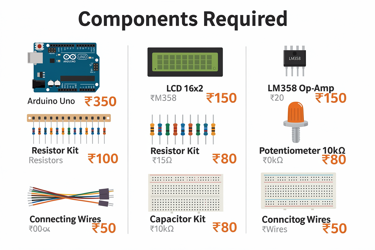
For this DIY oscilloscope project, you'll need the following components. All are easily available in the Indian market:
| Component | Specification | Price (₹) | Where to Buy in India |
|---|---|---|---|
| Arduino Uno | 16MHz ATmega328P, USB powered | 350 | Any electronic store, Amazon India |
| LCD 16x2 Display | I2C interface, blue backlight | 150 | Local market, online |
| Op-Amp LM358 | Dual low-power op-amp | 20 | Electronic component shops |
| Resistor Kit | Assorted values (100Ω to 1MΩ) | 100 | Local market |
| Capacitor Kit | 0.1µF to 100µF electrolytic | 80 | Electronics stores |
| Potentiometer 10kΩ | For voltage adjustment | 30 | Any electronics shop |
| Connecting Wires | Jumper wires set | 50 | Stores, online |
| Breadboard | 830 tie points | 120 | Local market |
| USB Cable | Type A to B | 50 | Computer accessories |
| 9V Battery | With connector | 40 | Local store |
| Total Cost | ~920 |
Additional Tools Needed:
- Soldering iron (optional)
- Multimeter (for testing)
- Computer with Python installed
- Breadboard jumper wires
- Small screwdriver set
Understanding the Circuit Design
Signal Conditioning Stage
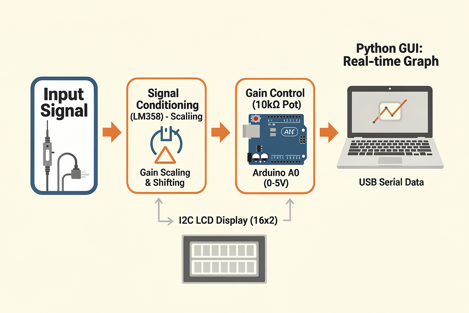
Before we dive into the circuit diagram, it's essential to understand why we need signal conditioning. Arduino's analog input pins can only read voltages between 0V and 5V, but many signals in electronics can exceed this range. The op-amp circuit we'll build will scale and shift the input voltage to fit within Arduino's measurable range.
Circuit Diagram
The circuit consists of three main stages:
- Signal Conditioning: Using LM358 op-amp to scale and shift signals
- Voltage Divider: Potentiometer for manual voltage adjustment
- Display Interface: I2C LCD for output visualization
Here's the complete circuit schematic:
- Input Stage: LM358 op-amp configured as a non-inverting amplifier
- Gain Control: Potentiometer adjusts the amplification factor
- Offset Adjustment: Second stage provides DC offset adjustment
- Output: Scaled signal sent to Arduino's analog pin A0
- Display: I2C LCD connected to Arduino's SDA and SCL pins
Step-by-Step Building Guide
Step 1: Setting Up the Arduino
First, install the Arduino IDE on your computer if you haven't already. For Indian users, you can download it from the official Arduino website. Connect your Arduino Uno to the computer via USB cable and verify it's working by running the built-in Blink example.
Step 2: Installing Required Libraries
Open the Arduino IDE and install the following libraries through the Library Manager:
- "LiquidCrystal_I2C" by Frank de Brabander
- "ArduinoJson" for data handling
Go to Tools > Manage Libraries and search for these libraries.
Step 3: Building the Signal Conditioning Circuit
- Place the LM358 op-amp on the breadboard
- Connect pin 1 and 5 to +5V supply
- Connect pin 4 and 6 to ground
- Configure pin 3 and 2 as the non-inverting amplifier input
- Connect the potentiometer as a variable resistor to adjust gain
- Add the voltage divider network for offset adjustment
Step 4: Connecting the I2C LCD
- Connect LCD's VCC to Arduino's 5V
- Connect GND to Arduino's ground
- Connect SDA (SDA) to Arduino A4 pin
- Connect SCL (SCL) to Arduino A5 pin
- Connect LCD's address pins to ground if using a 0x27 address (most common)
Step 5: Power Connection
Connect the 9V battery to the Arduino's barrel jack or use USB power. The breadboard supply rails can be powered from the Arduino's 5V pin.
Code Implementation
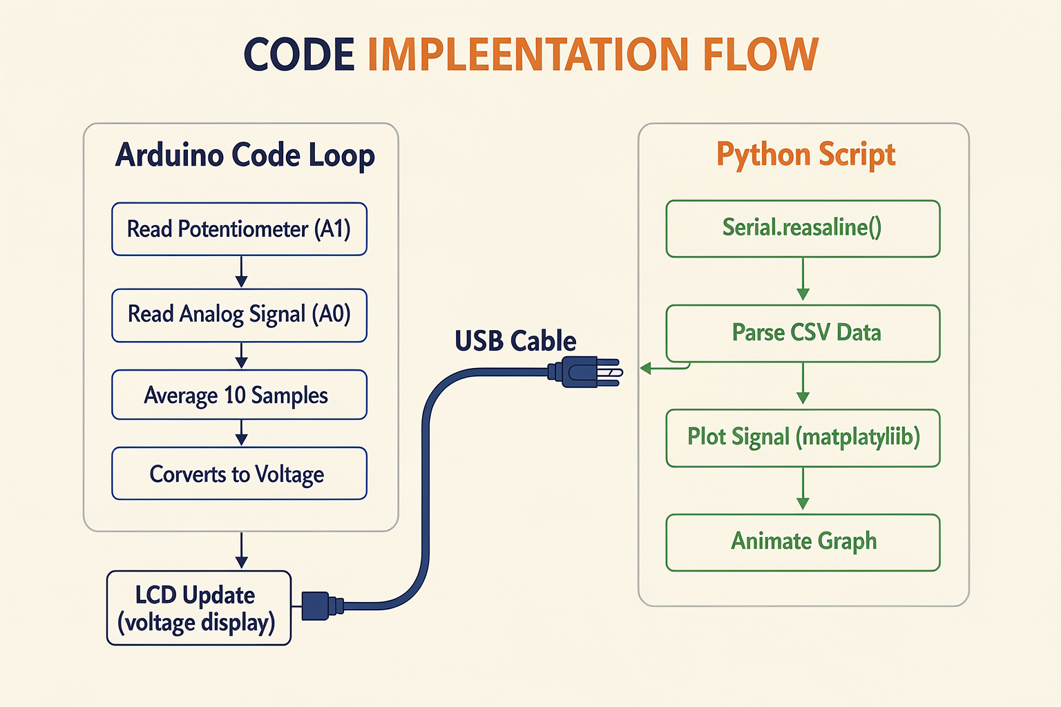
Now let's write the complete Arduino code for our DIY oscilloscope. We'll also create a Python script for better visualization.
Arduino Code
#include <LiquidCrystal_I2C.h>
#include <ArduinoJson.h>

// Initialize I2C LCD (0x27 is the default address)
LiquidCrystal_I2C lcd(0x27, 16, 2);

// Pin definitions
const int analogPin = A0;
const int potPin = A1;
const int numReadings = 64;  // Number of samples to average
float readings[numReadings];
int readIndex = 0;
int samples = 0;
float scaleFactor = 1.0;
float offset = 0.0;

void setup() {
  Serial.begin(9600);
  lcd.init();
  lcd.backlight();
  lcd.setCursor(0, 0);
  lcd.print("DIY Oscilloscope");
  delay(2000);
  lcd.clear();
  lcd.setCursor(0, 0);
  lcd.print("Ready...");
  lcd.setCursor(0, 1);
  lcd.print("Initializing...");
  delay(2000);
}

void loop() {
  // Read potentiometer for gain adjustment
  scaleFactor = map(analogRead(potPin), 0, 1023, 0.1, 2.0) / 10.0;

  // Read analog input
  readings[readIndex] = analogRead(analogPin);
  readIndex = (readIndex + 1) % numReadings;

  // Calculate average
  for (int i = 0; i < numReadings; i++) {
    samples += readings[i];
  }
  samples /= numReadings;

  // Convert to voltage (Arduino uses 0-1023 for 0-5V)
  float voltage = (samples / 1023.0) * 5.0;

  // Apply scaling and offset
  voltage = (voltage - offset) * scaleFactor;

  // Send data to Python via Serial
  Serial.print(voltage);
  Serial.print(",");
  Serial.println(scaleFactor);

  // Update LCD display
  updateDisplay(voltage);

  // Reset sample counter
  samples = 0;

  delay(50);  // Sample rate of 20 Hz
}

void updateDisplay(float voltage) {
  lcd.clear();

  // Display voltage reading
  lcd.setCursor(0, 0);
  lcd.print("V: ");
  lcd.print(voltage, 2);
  lcd.print("V");
Ready to start building?
Explore our collection of DIY kits and components. All project components mentioned in this blog are available in our store.
Browse All Projects