

Introduction
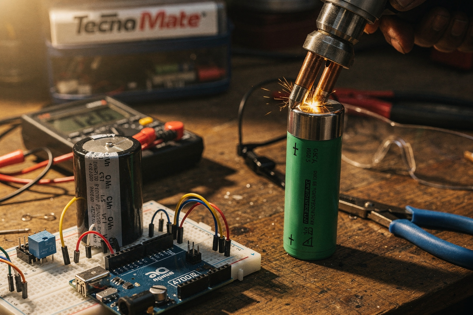
Building custom battery packs is a common project for engineering students and electronics enthusiasts in India. Whether you're working on an e-bike, power bank, or DIY electric vehicle, proper battery cell connection is crucial for safety and performance. Spot welding provides the most reliable connection, but commercial spot welders cost between ₹15,000 to ₹50,000 - quite an investment for students on a budget!
This comprehensive guide will walk you through building a fully functional DIY spot welder for under ₹3,000 using readily available components in India. The spot welder we'll build can handle 3-5A current, which is more than sufficient for most NiMH and Li-ion battery pack projects. Let's dive into this exciting DIY project that's perfect for your workshop!
Understanding Spot Welding Technology
Spot welding is a resistance welding process that joins metal sheets together by applying heat generated from resistance to electric current. For battery pack assembly, we use it to weld nickel strips to the tabs of battery cells (typically 18650, 21700, or similar cylindrical cells).
Why spot welding?
- Creates strong, low-resistance connections
- Prevents cell damage from solder heat
- Ensures uniform pressure distribution
- Ideal for series and parallel configurations
How it works:
- High current passes through overlapping metal tabs
- Resistance generates heat at the contact point
- Heat melts the metal, creating a weld
- Pressure maintains the connection as it cools
The key components we need are:
- Power source: Capacitor discharge system
- Control system: Arduino for timing and safety
- Welding electrodes: Tungsten or copper tips
- Safety features: Current limiting and cooling
Components Required
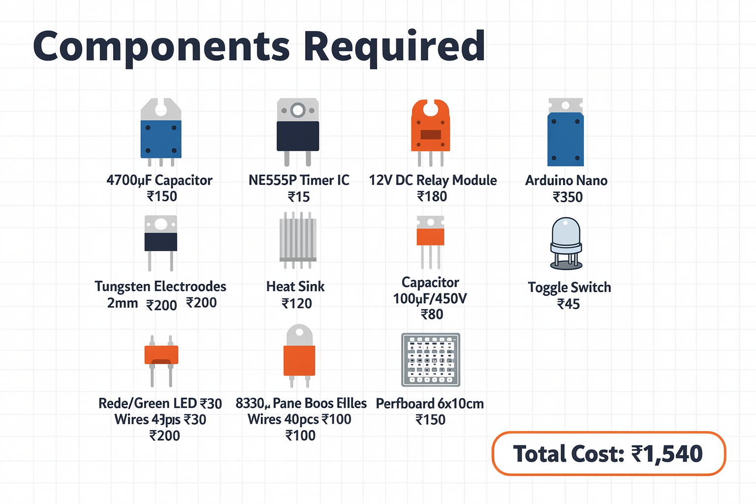
| Component | Specification | Price (₹) | Availability at TecnoMate |
|---|---|---|---|
| 4700µF Capacitor | 35V electrolytic | 150 | In Stock |
| 555 Timer IC | NE555P | 15 | In Stock |
| Relay Module | 12V DC, 5A | 180 | In Stock |
| Arduino Nano | ATmega328P | 350 | In Stock |
| Tungsten Electrodes | 2mm diameter | 200 | In Stock |
| Heat Sink | 10mm×30mm×30mm | 120 | In Stock |
| Capacitor 100µF/450V | Motor run capacitor | 80 | In Stock |
| Switch | Panel mount toggle | 45 | In Stock |
| LED Indicators | Green/Red 5mm | 30 | In Stock |
| Jumper Wires | 40-pin male-female | 100 | In Stock |
| Breadboard | 830 points | 180 | In Stock |
| Misc. PCB Board | Perfboard 6×10cm | 150 | In Stock |
Total Cost: Approximately ₹1,540
Note: Prices are indicative and may vary based on location and current market conditions in India.
Circuit Design and Theory
Our DIY spot welder operates on a capacitor discharge principle. The system stores energy in a large capacitor and releases it rapidly through the welding electrodes using a relay switched by a 555 timer or Arduino.
Basic Circuit Operation:
- Charging Phase: The 4700µF capacitor charges to 30V through a current-limiting resistor
- Discharge Phase: When triggered, the capacitor discharges through the welding electrodes
- Control Phase: Arduino monitors the process and controls the charging cycle
Power Calculations:
- Energy stored: E = ½CV² = ½ × 0.0047F × 30²V² ≈ 2.07J
- For a typical 18650 cell weld, we need 1-2J
- Our capacitor provides sufficient energy with safety margin
Safety Features:
- Current limiting resistor (typically 1Ω, 5W)
- Thermal fuse on the power supply
- Emergency stop button
- Capacitor discharge resistor for safe discharge
Step-by-Step Implementation Guide
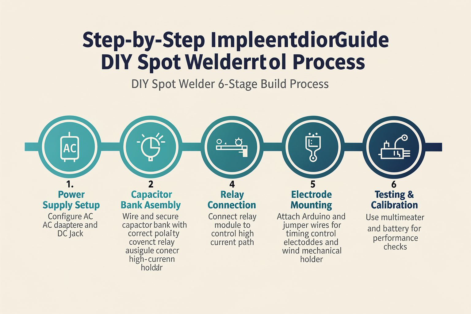
Step 1: Power Supply Setup
Start by setting up the power supply circuit. Connect the AC-DC adapter (12V, 2A) to the input of your power supply board. Add a bridge rectifier if using an AC adapter, followed by a 1000µF capacitor for smoothing.
AC Input → Bridge Rectifier → 1000µF Capacitor → 12V Regulator → 4700µF Welding Capacitor
Tip: Use a heatsink for the voltage regulator as it will dissipate significant heat.
Step 2: Charging Circuit Construction
Create a charging circuit using a current-limiting resistor. Calculate the resistor value using Ohm's law: R = V/I = 30V/1.3A ≈ 23Ω Select a 25Ω, 5W resistor for safety margin.
Connect a thermal fuse in series with the charging circuit for additional safety.
Step 3: Welding Electrode Assembly
Mount the tungsten electrodes on an adjustable frame. The electrodes should be:
- 2mm diameter tungsten rods
- Sharpened to a point for better contact
- Mounted in an insulated holder
- Adjustable for different cell sizes
Step 4: Control Circuit Assembly
Assemble the Arduino Nano circuit on the perfboard. Include:
- 555 timer for manual triggering
- Relay module for switching the capacitor discharge
- Push buttons for start/stop functionality
- LED indicators for system status
Step 5: Programming the Controller
Upload the control code to the Arduino Nano. The program should include:
- Button debouncing
- Capacitor charging control
- Safety timeout
- Status monitoring
Code Implementation
Here's the complete Arduino code for controlling your spot welder:
#include <Arduino.h>

// Pin definitions
const int RELAY_PIN = 9;
const int START_BUTTON = 2;
const int STOP_BUTTON = 3;
const int CHARGE_ENABLE = 4;
const int STATUS_LED = 13;
const int CURRENT_SENSE = A0;

// Global variables
bool welding = false;
bool charging = false;
unsigned long startTime = 0;
const int MAX_WELD_TIME = 3000; // 3 seconds max

void setup() {
  pinMode(RELAY_PIN, OUTPUT);
  pinMode(START_BUTTON, INPUT_PULLUP);
  pinMode(STOP_BUTTON, INPUT_PULLUP);
  pinMode(CHARGE_ENABLE, OUTPUT);
  pinMode(STATUS_LED, OUTPUT);
  pinMode(CURRENT_SENSE, INPUT);

  digitalWrite(CHARGE_ENABLE, LOW);
  digitalWrite(RELAY_PIN, LOW);

  Serial.begin(9600);
  Serial.println("Spot Welder Control System Initialized");
}

void loop() {
  checkButtons();
  monitorSystem();

  if (welding) {
    performWeld();
  } else {
    handleIdle();
  }

  delay(10);
}

void checkButtons() {
  if (digitalRead(START_BUTTON) == LOW && !welding) {
    startWeld();
  }

  if (digitalRead(STOP_BUTTON) == LOW && welding) {
    stopWeld();
  }
}

void checkButtons() {
  if (digitalRead(START_BUTTON) == LOW && !welding) {
    startWeld();
  }

  if (digitalRead(STOP_BUTTON) == LOW && welding) {
    stopWeld();
  }
}

void startWeld() {
  welding = true;
  startTime = millis();

  // Start charging the capacitor
  digitalWrite(CHARGE_ENABLE, HIGH);
  digitalWrite(STATUS_LED, HIGH);

  Serial.println("Starting weld sequence...");
  delay(1000); // Wait for capacitor to charge

  // Activate welding relay
  digitalWrite(RELAY_PIN, HIGH);

  Serial.println("WELDING IN PROGRESS - CAUTION!");
}

void stopWeld() {
  welding = false;
  digitalWrite(RELAY_PIN, LOW);
  digitalWrite(STATUS_LED, LOW);

  Serial.println("Weld sequence stopped.");
}

void performWeld() {
  unsigned long currentTime = millis();

  if (currentTime - startTime > MAX_WELD_TIME) {
    stopWeld();
    delay(2000);
    digitalWrite(CHARGE_ENABLE, LOW);
    Serial.println("Weld timeout reached.");
    return;
  }

  // Read current sensor (if implemented)
  int currentReading = analogRead(CURRENT_SENSE);
  float current = (currentReading / 1023.0) * 5.0;

  Serial.print("Current: ");
  Serial.print(current);
  Serial.println("A");

  // Optional: Implement current limiting
  if (current > 6.0) {
    Serial.println("Warning: High current detected!");
  }
}

void handleIdle() {
  if (charging) {
    digitalWrite(CHARGE_ENABLE, HIGH);
    delay(100);
    digitalWrite(CHARGE_ENABLE, LOW);
  }

  if (!digitalRead(START_BUTTON)) {
    delay(50); // Debounce
    if (digitalRead(START_BUTTON) == LOW) {
      startWeld();
    }
  }
}

void monitorSystem() {
  // Add system monitoring code here
  // Temperature monitoring, voltage checks, etc.
}
Safety Considerations
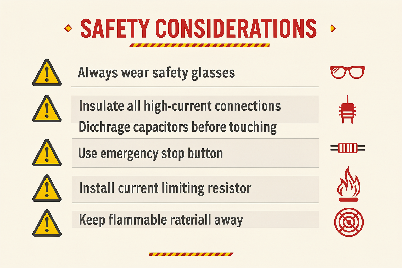
CRITICAL SAFETY WARNINGS:
-
High Voltage and Current: This device handles dangerous levels of electricity. Always wear safety gear including:
- Insulated gloves
- Safety goggles
- Closed-toe shoes
-
Capacitor Safety: The 4700µF capacitor can store lethal charge:
- Always discharge before handling
- Use a resistor with proper power rating
- Never short the terminals intentionally
-
Electrical Isolation: Keep high-voltage and low-voltage sections separate. Use proper insulation and mounting.
-
Ventilation: Welding produces fumes. Work in a well-ventilated area or use a fume extractor.
-
Fire Safety: Keep a fire extinguisher rated for electrical fires nearby.
Testing and Calibration
Initial Testing:
-
Without Batteries:
- Test the welding with dummy load (wire piece)
- Verify proper capacitor discharge
- Check electrode alignment
-
With Test Cells:
- Start with damaged cells
- Practice on single cells first
- Gradually increase to multi-cell assemblies
Calibration Parameters:
- Weld Time: Start with 500ms, adjust based on results
- Pressure: Adjust electrode pressure for good contact
- Current: Monitor if using current limiting
Troubleshooting
| Problem | Possible Cause | Solution |
|---|---|---|
| No weld occurs | Capacitor not charged | Check charging circuit, verify capacitor voltage |
| Weak welds | Electrode pressure too low | Adjust electrode mounting for better pressure |
| Overheating | Heat sink inadequate | Add larger heat sink or cooling fan |
| Relay clicking but no weld | Relay contacts dirty | Clean relay contacts, check relay rating |
| System resets | Power supply voltage sag | Use higher current adapter, add input capacitor |
| Uneven welds | Electrode alignment issue | Realign electrodes, check for wear |
| Arcing | Electrodes too close | Increase electrode gap, check for contamination |
| Capacitor fails | Overvoltage condition | Add voltage regulation, check charging circuit |
Common Pitfalls to Avoid:
- Insufficient Cooling: The MOSFET and relay will overheat without proper heat sinking
- Poor Connections: Loose connections can cause arcing and damage components
- Wrong Capacitor Rating: Using a capacitor with insufficient voltage rating can cause failure
- Ignoring Safety: Never skip safety features - they're there for a reason
Frequently Asked Questions
Yes! All components mentioned are readily available at electronics markets like SP Road in Bangalore or Lamington Road in Mumbai. You can substitute parts with equivalents of similar specifications. For example, instead of an Arduino Nano, you can use any ATmega328P-based board available locally.
Ready to start building?
Explore our collection of DIY kits and components. All project components mentioned in this blog are available in our store.
Browse All Projects