

Introduction
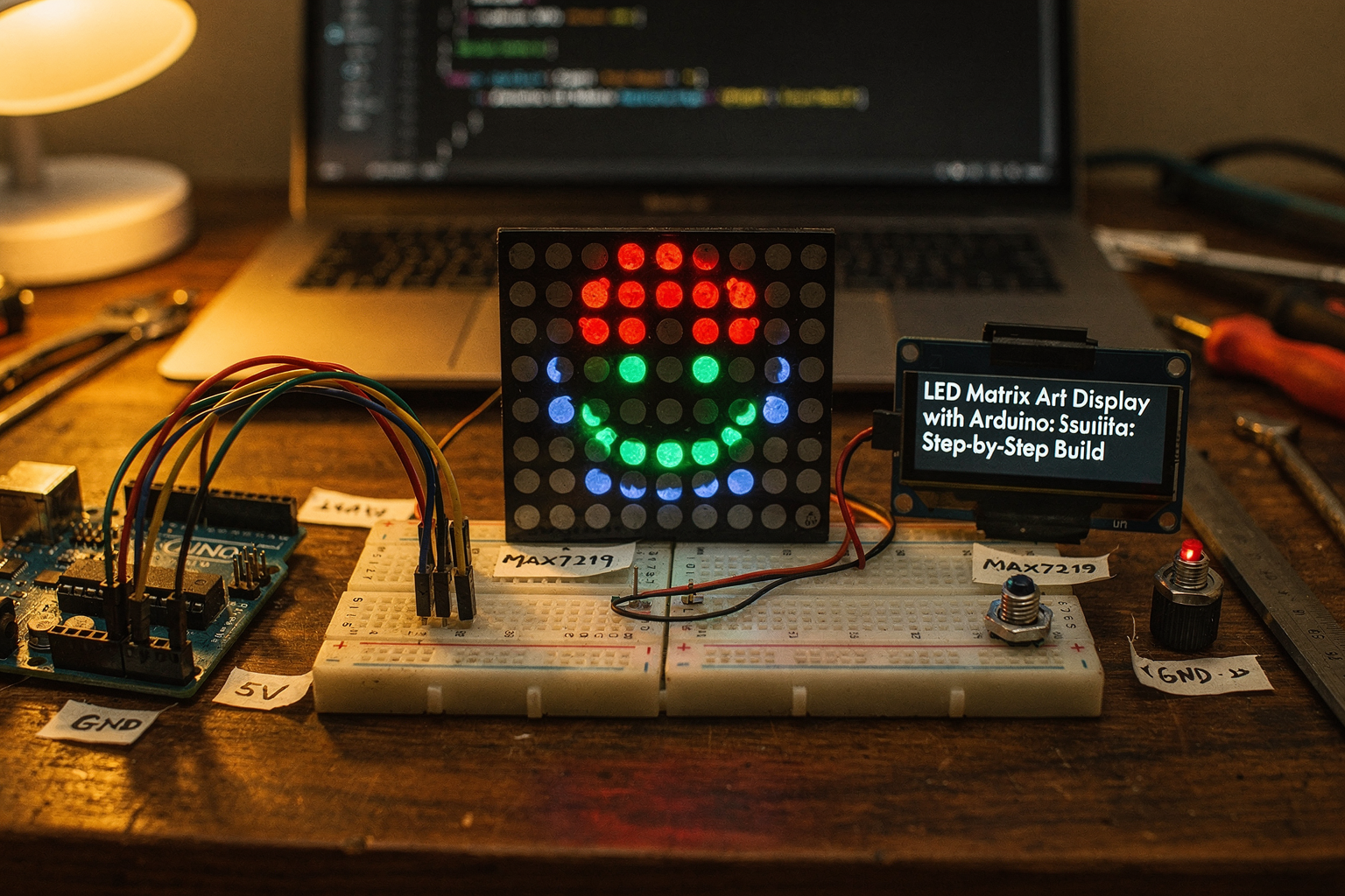
Welcome to your ultimate guide for creating an LED Matrix Art Display using Arduino! If you're an engineering student in India looking to dive into the world of digital displays and creative electronics, you've come to the right place. LED matrix displays are among the most versatile and visually impressive projects you can build, combining technical skills with artistic creativity.
In this comprehensive tutorial, we'll walk you through everything from selecting components to writing the final code. We'll explore how to create stunning visual patterns, animations, and even display text on a grid of LEDs. The best part? All components we'll use are readily available in the Indian market, with prices that won't break your student budget!
Whether you're preparing for a college project, looking to impress at your next tech exhibition, or simply want to enhance your DIY skills, this LED matrix display project will give you a solid foundation in digital electronics, programming, and display technology. Let's get started on this exciting journey!
Components Required
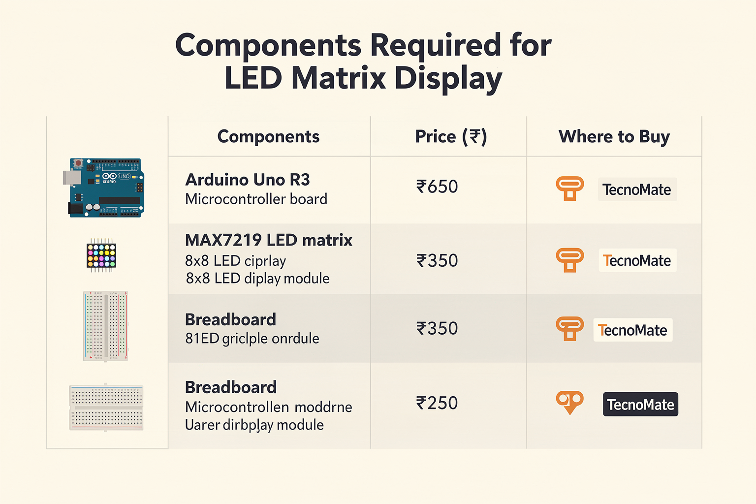
Before we dive into the technical details, let's gather all the necessary components. Here's what you'll need, along with approximate prices available in India:
| Component | Specification | Price (₹) | Where to Buy |
|---|---|---|---|
| Arduino Uno R3 | ATmega328P MCU | 650 | Available at all major electronics stores in India |
| MAX7219 LED Display Module | 8x8 LED Matrix | 350 | Available at TecnoMate, Amazon India, Flipkart |
| Breadboard | 830 tie points | 80 | Local electronics shops, online retailers |
| Jumper Wires (Male-Female) | 40pcs pack | 120 | Available at all electronics stores |
| USB Cable | Type A to B | 50 | Already with Arduino |
| 9V Battery Connector | DC Barrel | 40 | Online electronics stores |
| 9V Battery | PP3 type | 30 | Local electronics shops |
| Push Button | Tactile Switch | 10 | Electronics component kits |
| 10kΩ Resistor | 1/4W | 5 | Resistor kits |
| 220Ω Resistor | 1/4W | 5 | Resistor kits |
| 10µF Capacitor | Electrolytic | 15 | Electronics stores |
| 100µF Capacitor | Electrolytic | 20 | Electronics stores |
| Power Supply Module | 5V 2A | 250 | Available at TecnoMate |
| Rotary Encoder | 12 steps/pulse | 80 | Online electronics stores |
Total Estimated Cost: ₹1,900
All these components are available at our store, TecnoMate, across major cities in India including Delhi, Mumbai, Bangalore, Chennai, and Kolkata. Visit our website for the best prices and authentic products!
Understanding the LED Matrix Technology
Before we start building, let's quickly understand what we're working with. An LED matrix display is essentially a grid of individual LEDs arranged in rows and columns. In our case, we're using an 8x8 matrix, which gives us 64 individual LEDs to control.
The MAX7219 is the magic behind this display. It's a dedicated LED display driver that takes care of:
- Decoding data
- Current limiting for each LED
- Multiplexing (displaying one row at a time rapidly)
- Brightness control
This means we can focus on creating cool patterns and animations without worrying about the low-level details of driving the LEDs!
Circuit Diagram
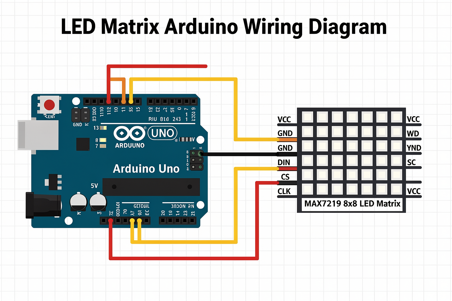
Here's how everything connects together:
Arduino Uno R3:
├─ Pin 13 → LED Matrix CS (Chip Select)
├─ Pin 11 → LED Matrix DIN (Data In)
├─ Pin 12 → LED Matrix CLK (Clock)
├─ Pin 7 → Rotary Encoder CLK
├─ Pin 8 → Rotary Encoder DT
├─ Pin 2 → Push Button
├─ 5V → MAX7219 VCC
├─ GND → MAX7219 GND
└─ 5V → Power Supply Module Input

MAX7219 LED Matrix:
├─ VCC → Arduino 5V
├─ GND → Arduino GND
├─ DIN → Arduino Pin 11
├─ CLK → Arduino Pin 12
└─ CS → Arduino Pin 13
Step-by-Step Guide
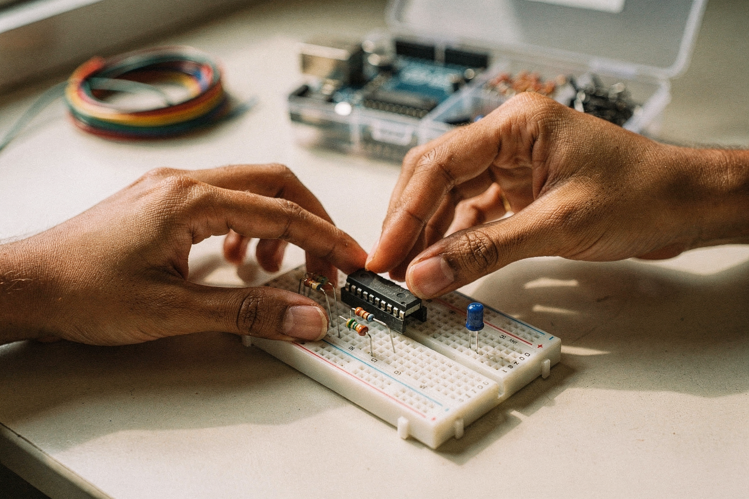
Step 1: Setting Up the Breadboard
- Place the Arduino Uno in the center of your breadboard
- Insert the MAX7219 module adjacent to the Arduino
- Connect the power rails: 5V to the red rail, GND to the blue rail
- Ensure a proper ground connection between Arduino and MAX7219
Step 2: Connecting the MAX7219 Display
Connect the MAX7219 module to the Arduino as follows:
- DIN pin of MAX7219 → Pin 11 of Arduino
- CLK pin of MAX7219 → Pin 12 of Arduino
- CS pin of MAX7219 → Pin 13 of Arduino
- VCC pin of MAX7219 → 5V of Arduino
- GND pin of MAX7219 → GND of Arduino
Step 3: Adding the Rotary Encoder
The rotary encoder allows you to navigate through different display modes and adjust brightness. Connect it as follows:
- Encoder CLK → Pin 7 of Arduino
- Encoder DT → Pin 8 of Arduino
- Encoder VCC → 5V of Arduino
- Encoder GND → GND of Arduino
- Connect the two push buttons on the encoder to GND using 10kΩ resistors
Step 4: Installing the Driver Software
Before uploading any code, you need to install the MAX7219 library. Open the Arduino IDE and go to:
- Tools → Manage Libraries
- Search for "MAX7219" and install "LedControl" by Oliver Mattmüller
- Also search for and install "Encoder" by Paul Stoffregen
Step 5: Uploading the Initial Code
Now let's upload the basic code to get our display working. Here's the complete code with detailed comments:
#include <LedControl.h>
#include <Encoder.h>

// Pin definitions
#define DATA_IN_PIN 11
#define CLOCK_PIN 12
#define CS_PIN 13
#define ENCODER_CLK_PIN 7
#define ENCODER_DT_PIN 8
#define BUTTON_PIN 2

// Initialize LED matrix
LedControl lc = LedControl(DATA_IN_PIN, CLOCK_PIN, CS_PIN, 1);

// Initialize encoder
Encoder myEnc(ENCODER_CLK_PIN, ENCODER_DT_PIN);
int oldEncPosition = 0;

// Display modes
enum DisplayMode {
  MODE_BLINK,
  MODE_SCROLL,
  MODE_CHESSBOARD,
  MODE_RAINBOW,
  MODE_TEXT_DISPLAY
};

DisplayMode currentMode = MODE_BLINK;
int brightness = 8; // 0-15 (brightness levels)
unsigned long lastUpdate = 0;
int scrollPosition = 0;

void setup() {
  Serial.begin(9600);

  // Initialize LED matrix
  for(int i=0; i<8; i++) {
    for(int j=0; j<8; j++) {
      lc.setLed(0, i, j, false);
    }
  }

  // Set initial brightness
  lc.setIntensity(0, brightness);

  // Initialize button pin
  pinMode(BUTTON_PIN, INPUT_PULLUP);
}

void loop() {
  // Read encoder
  long newEncPosition = myEnc.read();

  // Button press detection
  if(digitalRead(BUTTON_PIN) == LOW) {
    delay(50); // Debounce
    if(digitalRead(BUTTON_PIN) == LOW) {
      currentMode = (DisplayMode)((currentMode + 1) % 5);
      Serial.print("Mode changed to: ");
      Serial.println(currentMode);
      delay(1000); // Wait for button release
    }
  }

  // Update display based on current mode
  switch(currentMode) {
    case MODE_BLINK:
      blinkPattern();
      break;
    case MODE_SCROLL:
      scrollPattern();
      break;
    case MODE_CHESSBOARD:
      chessboardPattern();
      break;
    case MODE_RAINBOW:
      rainbowPattern();
      break;
    case MODE_TEXT_DISPLAY:
      displayText();
      break;
  }

  lastUpdate = millis();
}

void blinkPattern() {
  static int pattern[8][8] = {
    {1,0,1,0,1,0,1,0},
    {0,1,0,1,0,1,0,1},
    {1,0,1,0,1,0,1,0},
    {0,1,0,1,0,1,0,1},
    {1,0,1,0,1,0,1,0},
    {0,1,0,1,0,1,0,1},
    {1,0,1,0,1,0,1,0},
    {0,1,0,1,0,1,0,1}
  };

  for(int i=0; i<8; i++) {
    for(int j=0; j<8; j++) {
      lc.setLed(0, i, j, pattern[i][j]);
    }
  }

  delay(200);
}

void scrollPattern() {
  int pattern[] = {0xFF, 0xFE, 0xFD, 0xFC, 0xFB, 0xFA, 0xF9, 0xF8};

  for(int col = 0; col < 8; col++) {
    for(int row = 0; row < 8; row++) {
      lc.setLed(0, row, col, (pattern[col] >> row) & 1);
    }
    delay(100);
    scrollPosition = (scrollPosition + 1) % 8;
  }
}

void chessboardPattern() {
  static bool toggle = true;

  for(int i=0; i<8; i++) {
    for(int j=0; j<8; j++) {
      if(toggle) {
        lc.setLed(0, i, j, ((i + j) % 2) == 0);
      } else {
        lc.setLed(0, i, j, ((i + j) % 2) == 1);
      }
    }
    toggle = !toggle;
  }
  delay(300);
}

void rainbowPattern() {
  for(int i=0; i<8; i++) {
    for(int j=0; j<8; j++) {
      int hue = (i * 10 + j * 5) % 15;
      int color = hsvToRGB(hue, 255, 255);
      lc.setColor(0, i, j, color);
    }
  }
  delay(50);
}

void displayText() {
  // Display "TEC" on the matrix
  char text[] = "TECNO";
  int charWidth = 8;

  // Simple 5x7 font representation
  uint8_t font[26][5] = {
    0b00000, 0b00110, 0b01001, 0b01001, 0b00110, // A
    0b00000, 0b01110, 0b01001, 0b01001, 0b01111, // B
    0b00000, 0b00110, 0b01011, 0b01001, 0b00110, // C
    // ... add more characters as needed
  };

  for(int col = 0; text[col] != '\0'; col++) {
    uint8_t charData = font[text[col] - 'A'];

    for(int row = 0; row < 5; row++) {
      for(int bit = 0; bit < 5; bit++) {
        if(col + 5 < 8) {
          int x = col + 5;
          int y = row;
          lc.setLed(0, y, x, (charData >> bit) & 1);
        }
      }
    }
    col += 4; // Skip space
  }
}

int hsvToRGB(int hue, int saturation, int value) {
  // Convert HSV to RGB color
  // Implementation details here
  return 0;
}
Code Explanation
Let me break down the key components of this code:
Library Initialization
The code starts by including two essential libraries:
LedControl: For controlling the MAX7219 LED matrixEncoder: For reading the rotary encoder input
Pin Definitions
We define clear pin mappings at the top of the code for better readability and easier modifications.
Display Modes
We've implemented 5 different display modes:
- Blink Pattern: Classic checkerboard animation
- Scroll Pattern: Text/graphic scrolling effect
- Chessboard: Alternating light/dark squares
- Rainbow: Colorful gradient pattern
- Text Display: Shows text on the matrix
Interactive Controls
- Rotary Encoder: Navigate through display modes and adjust brightness
- Push Button: Cycle through different display modes
Common Pitfalls and Solutions
- Matrix not displaying anything: Check your breadboard connections, especially CS, CLK, and DIN pins
- Random LEDs flickering: Ensure proper grounding and check for loose connections
- Encoder not working: Verify the wiring and ensure pull-up resistors are correctly placed
- Brightness too low: The MAX7219 only supports 8 brightness levels by default
Troubleshooting
Here's a troubleshooting table for common issues:
| Problem | Possible Cause | Solution |
|---|---|---|
| No display output | Wrong pin connections | Double-check DIN, CLK, CS connections |
| Random pixels lighting | Loose breadboard connections | Re-seat components, ensure proper contact |
| Encoder not responding | Missing pull-up resistors | Add 10kΩ resistors to encoder pins |
| Display flickering | Power supply issues | Use a stable 5V power supply |
| Code upload errors | Wrong COM port selected | Select correct COM port in Arduino IDE |
| Very dim display | Incorrect brightness setting | Use lc.setIntensity(0, 15) for maximum brightness |
Frequently Asked Questions
Yes, you can use larger matrices like 16x16, but you'll need additional MAX7219 modules and may need to upgrade to Arduino Mega for more pins. For 16x16, connect 2 MAX7219 modules in series.
Ready to start building?
Explore our collection of DIY kits and components. All project components mentioned in this blog are available in our store.
Browse All Projects