

Introduction
Welcome to your comprehensive guide to operational amplifiers (op-amps)! If you're an engineering student or DIY enthusiast in India, you've likely encountered op-amps in your circuits, textbooks, or projects. These remarkable components are the workhorses of analog electronics, forming the backbone of countless applications from audio amplifiers to sensor interfaces.
In this guide, we'll demystify op-amp circuits, focusing specifically on three fundamental configurations: inverting amplifiers, non-inverting amplifiers, and voltage followers (buffers). Whether you're designing your first audio amplifier or interfacing with a microcontroller, understanding these circuits is crucial for your electronics journey.
Let's start by understanding what makes op-amps so special and why they're indispensable in modern electronics.
Understanding the Op-Amp Basics
An operational amplifier, or op-amp, is a high-gain electronic voltage amplifier with differential inputs and a single output. In its ideal form, an op-amp has infinite input impedance, zero output impedance, infinite open-loop gain, and infinite bandwidth.
Key Pin Configuration
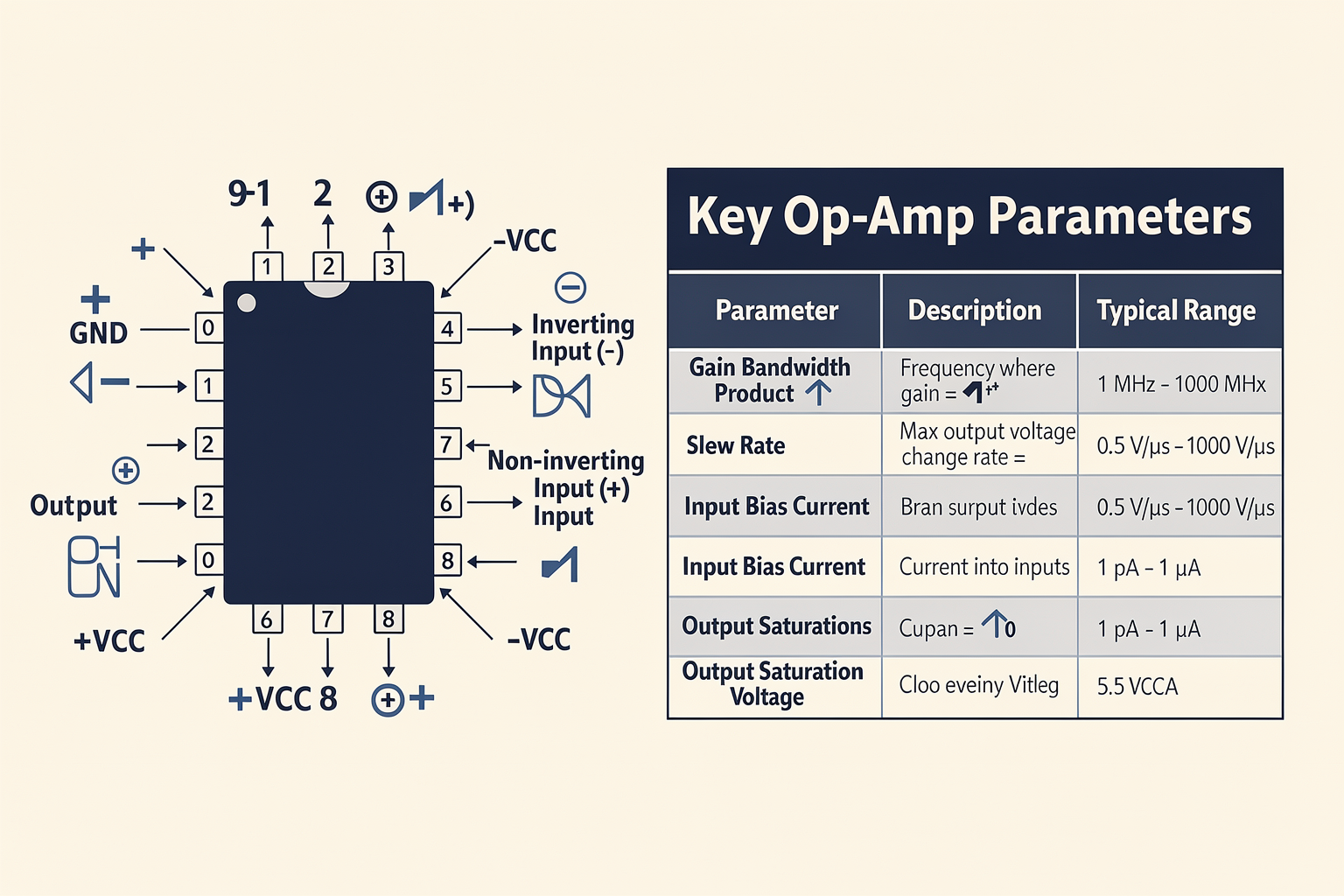
Most standard op-amps come in an 8-pin DIP package with the following pinout:
    1   2   3   4   5   6   7   8
   ┌───┬───┬───┬───┬───┬───┬───┬───┐
   │ 1 │ 2 │ 3 │ 4 │ 5 │ 6 │ 7 │ 8 │
   └───┴───┴───┴───┴───┴───┴───┴───┘
   |   |   |   |   |   |   |   |   |
 GND  NC  NC  INV  OUT NON-INV  VCC VCC
- Pin 1: Ground (GND)
- Pin 2: Inverting Input (-)
- Pin 3: Non-inverting Input (+)
- Pin 6: Output
- Pin 7: Positive Supply (+VCC)
- Pin 8: Negative Supply (-VCC)
Note: Some op-amps like the LM358 use different pinouts, so always verify your specific component!
Key Parameters to Consider
When selecting an op-amp for your project, consider these crucial parameters:
| Parameter | Description | Typical Value Range |
|---|---|---|
| Gain Bandwidth Product | Frequency at which gain drops to 1 | 1 MHz - 1000 MHz |
| Slew Rate | Maximum rate of output voltage change | 0.5 V/μs - 1000 V/μs |
| Input Bias Current | Current flowing into input terminals | 1 pA - 1 μA |
| Output Saturation Voltage | Voltage difference from supply rails | 0.5 V - 5 V |
Inverting Amplifier Configuration
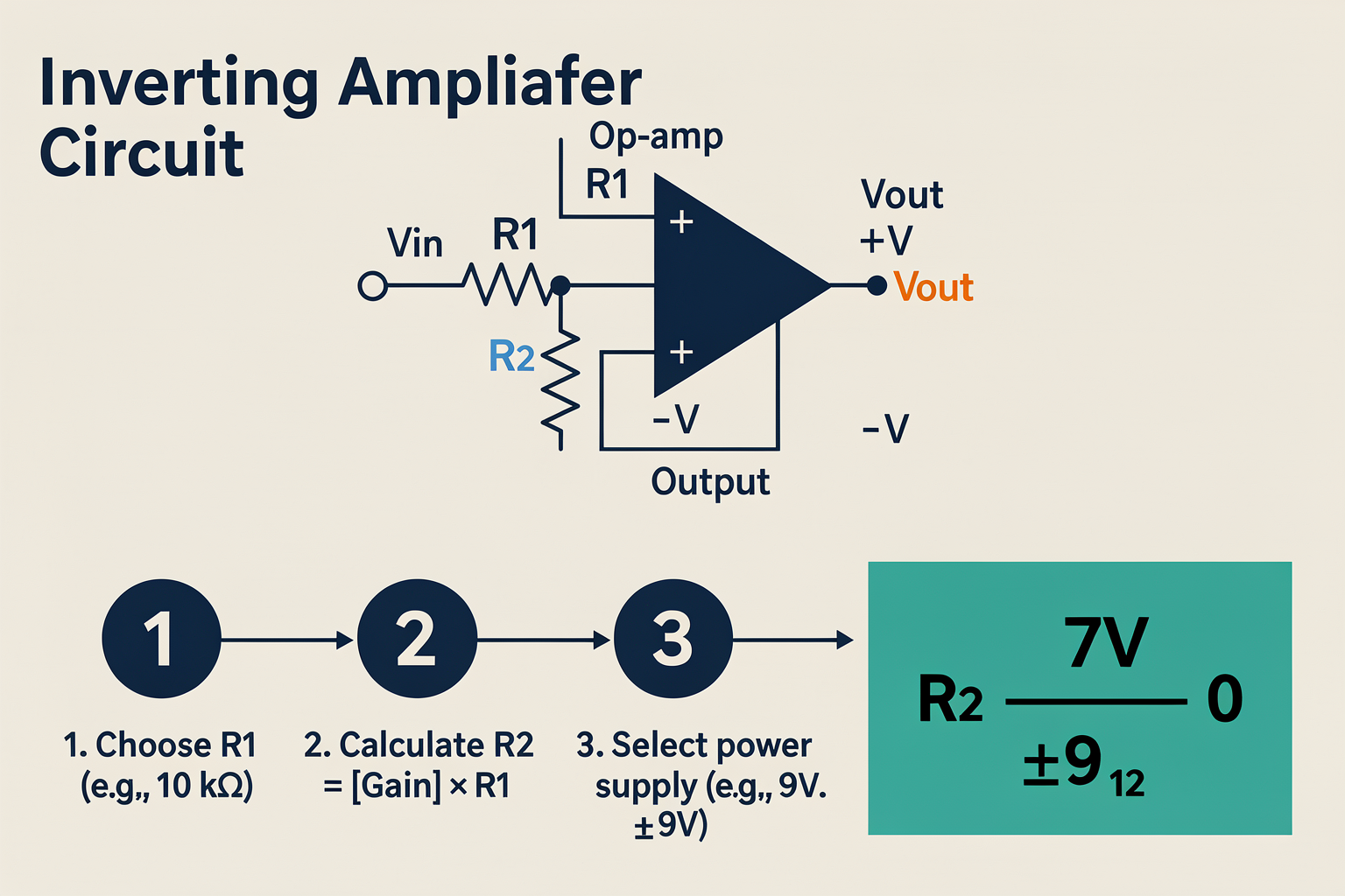
The inverting amplifier is one of the most fundamental op-amp circuits. It inverts the input signal and provides amplification based on the ratio of feedback and input resistors.
Circuit Diagram
           R1
Input --|---/\/\---|+
          |       |
          |       |
          |      \-
          |       \--- Output
          |       |
 GND -----+-------+---- GND
           R2
Mathematical Analysis
The gain of an inverting amplifier is given by:
Gain = -R2/R1
The negative sign indicates the phase inversion (180° phase shift).
Design Procedure
Let's design a simple inverting amplifier with a gain of -10:
- Choose R1: Start with a convenient value, typically 10 kΩ
- Calculate R2: R2 = |Gain| × R1 = 10 × 10 kΩ = 100 kΩ
- Select power supply: For audio applications, ±9V is common
Practical Example: Microcontroller Signal Conditioning Circuit
Here's a practical example of conditioning a microcontroller PWM signal for an audio application:
# Example: PWM to Analog conversion using inverting amplifier
# This Python code simulates the behavior

import numpy as np
import matplotlib.pyplot as plt

# Simulate PWM signal (0-5V from microcontroller)
pwm_signal = np.random.randint(0, 1024, 1000) * 5.0 / 1024
time = np.linspace(0, 1, 1000)

# Inverting amplifier with gain of -2
gain = -2
amplified_signal = pwm_signal * gain

# Plot the results
plt.figure(figsize=(12, 6))
plt.plot(time, pwm_signal, label='Original PWM (0-5V)', alpha=0.7)
plt.plot(time, amplified_signal, label='Amplified (-2x)', alpha=0.7)
plt.xlabel('Time (s)')
plt.ylabel('Voltage (V)')
plt.title('PWM Signal Conditioning with Inverting Amplifier')
plt.legend()
plt.grid(True)
plt.show()
This circuit is particularly useful when you need to amplify signals while maintaining their inverted polarity, common in audio processing chains.
Common Applications
- Audio amplifiers (phase inversion stages)
- Summing amplifiers
- Integrators and differentiators
- Signal inversion for feedback systems
Non-Inverting Amplifier Configuration
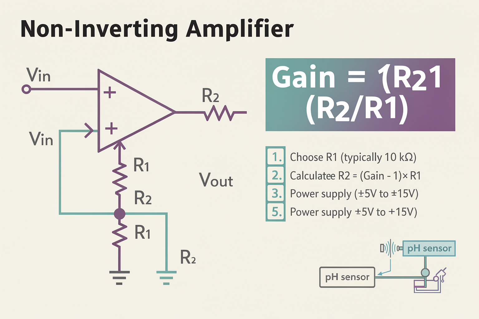
The non-inverting amplifier maintains the input signal's polarity while providing gain through positive feedback.
Circuit Diagram
           R1
Input ---|+---+---/\/\---+
          |   |       |
          |   |       |
          |  \- |       |
          |    \--- Output
          |      |
 GND -----+--------+---- GND
           R2
Mathematical Analysis
The gain of a non-inverting amplifier is:
Gain = 1 + (R2/R1)
Since the gain is always positive, the output maintains the same phase as the input.
Design Procedure
Let's design a non-inverting amplifier with a gain of 5:
- Choose R1: Typically 10 kΩ
- Calculate R2: (Gain - 1) × R1 = (5 - 1) × 10 kΩ = 40 kΩ
- Power supply: Same consideration as inverting amplifier
Practical Example: Sensor Signal Amplification
Many sensors produce small signals that need amplification without polarity inversion:
// Arduino example: Amplifying a temperature sensor signal
// Using non-inverting configuration for pH sensor
#define SENSOR_PIN A0
#define GAIN 10

void setup() {
  Serial.begin(9600);
  analogReference(EXTERNAL); // For better precision

  // Initialize ADC for higher resolution
  analogWriteResolution(12);
}

void loop() {
  // Read raw sensor value
  int rawValue = analogRead(SENSOR_PIN);

  // Convert
Ready to start building?
Explore our collection of DIY kits and components. All project components mentioned in this blog are available in our store.
Browse All Projects