

Introduction
Welcome to your first comprehensive oscilloscope tutorial! If you're an engineering student in India or a DIY electronics enthusiast, you've probably heard about oscilloscopes but wondered how to actually use one. Don't worry – we're here to guide you through everything you need to know about this essential tool.
An oscilloscope is like an X-ray for your electronic signals. While a multimeter tells you if a circuit is "on" or "off," an oscilloscope shows you exactly what's happening to your signals over time. Whether you're debugging a microcontroller circuit, measuring PWM signals, or analyzing audio frequencies, an oscilloscope is your best friend.
In this tutorial, we'll cover everything from basic setup to advanced measurements, with practical examples relevant to Indian engineering students and hobbyists. We'll also reference components and tools available at TecnoMate, India's #1 DIY Electronics Project Store.
Understanding Oscilloscope Basics
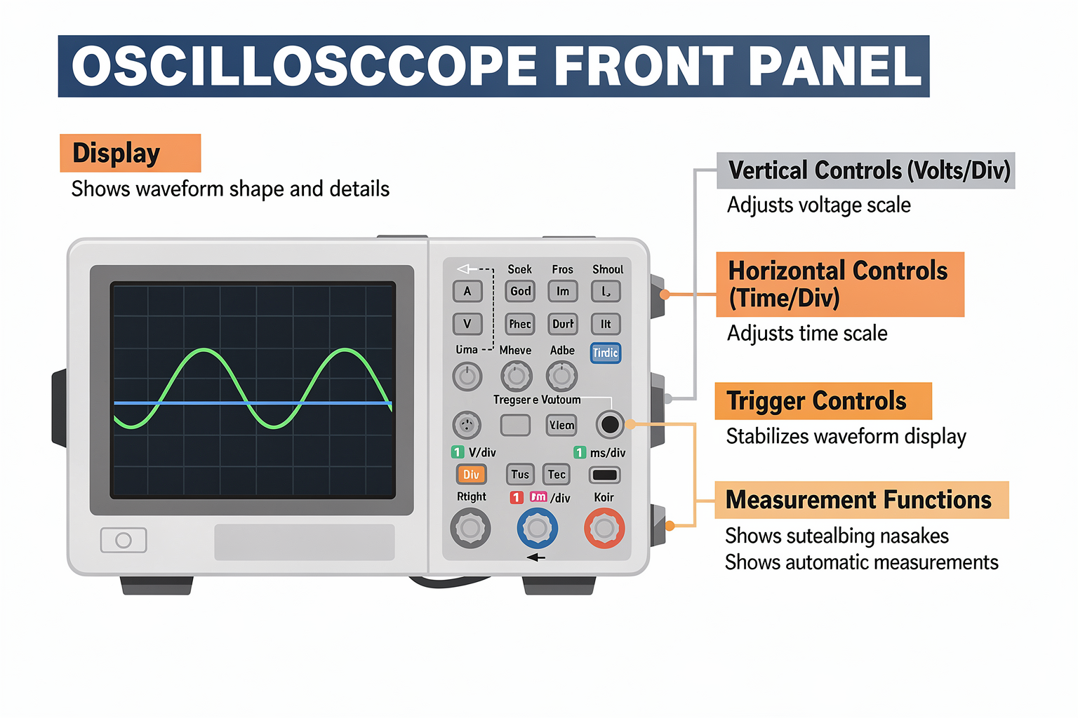
Before we dive in, let's understand what you're looking at. An oscilloscope displays voltage as a function of time, creating waveforms that tell you about your signal's behavior. The main components include:
- Display: Shows the waveform
- Vertical Controls: Adjust voltage scale (volts/div)
- Horizontal Controls: Adjust time scale (seconds/div)
- Trigger Controls: Stabilizes the waveform display
- Measurement Functions: Automatic voltage and time measurements
Key Oscilloscope Specifications
| Parameter | Beginner Scope | Advanced Scope | Price Range (₹) |
|---|---|---|---|
| Bandwidth | 20-100 MHz | 100+ MHz | 3,000 - 25,000 |
| Channels | 2 | 4+ | - |
| Memory | 1-2 MSpt | 12+ MSpt | - |
| Sampling Rate | 0.5-2 GSa/s | 5+ GSa/s | - |
Components Required for Your First Setup
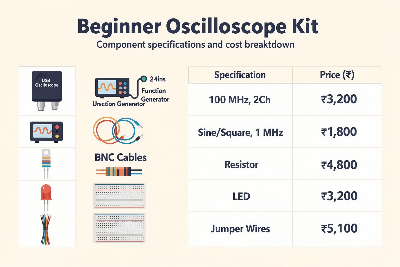
For this tutorial, you'll need a few essential components. Don't worry – all of these are available at TecnoMate with competitive pricing and fast delivery across India:
| Component | Specification | Price (₹) | Availability |
|---|---|---|---|
| USB Oscilloscope | 100MHz, 2Ch | 3,200 | In Stock |
| Function Generator | 0-20 MHz | 2,800 | In Stock |
| BNC Cables | 2 pieces | 150 | In Stock |
| Resistive Load | 1kΩ, 1W | 20 | In Stock |
| LED | 5mm, Red | 5 | In Stock |
| Breadboard | 830 points | 120 | In Stock |
| Jumper Wires | 40pcs | 80 | In Stock |
Total Cost: ₹6,555 – An affordable starting point for any electronics enthusiast!
Getting Started with Your Oscilloscope
Step 1: Physical Setup
First, let's connect everything properly. Here's a simple circuit to start with:
- Connect your function generator output to Channel 1 (CH1) of the oscilloscope using a BNC cable
- Connect a 1kΩ resistor between CH1 and ground
- Connect CH2 to ground using another BNC cable
- Power up both devices
// Simple Arduino code to test your oscilloscope setup
// This generates a square wave for testing
void setup() {
  pinMode(9, OUTPUT);  // PWM pin for signal generation
  Serial.begin(9600);
}

void loop() {
  digitalWrite(9, HIGH);   // Set pin high
  delayMicroseconds(500);  // Wait 500 microseconds
  digitalWrite(9, LOW);    // Set pin low
  delayMicroseconds(500);  // Wait 500 microseconds
}
Step 2: Basic Oscilloscope Controls
Let's understand the basic controls you'll use most often:
Vertical Controls (CH1 & CH2)
- Volts/Division (V/div): Sets the voltage scale for each channel
- Position: Moves the waveform up or down
- Coupling: Select between AC, DC, or Ground coupling
- Invert: Flips the waveform vertically
Horizontal Controls
- Time/Division (s/div): Sets the time scale
- Position: Moves the waveform left or right
- Single/Auto: Controls acquisition mode
Trigger Controls
- Trigger Source: Select CH1, CH2, or Auto
- Trigger Type: Edge, Slope, or Video
- Trigger Level: Sets the voltage level for triggering
Step 3: Making Your First Measurement
Let's measure a simple sine wave:
- Set the function generator to 1kHz sine wave, 2Vpp
- Connect CH1 to the function generator output
- Set CH1 Volts/div to 500mV (0.5V)
- Set Time/div to 1ms (0.001s)
- Adjust trigger level to around 1V
You should now see a stable sine wave on your screen. Let's measure it:
- Frequency: Measure the time period (T) and calculate f = 1/T
- Amplitude: Count divisions vertically and multiply by V/div
- Phase: Use the measurement tools for phase difference between channels
Advanced Oscilloscope Techniques
Measuring Digital Signals
Digital signals from microcontrollers need different settings:
// Arduino code to generate PWM signal
void setup() {
  TCCR1A = 0;
  TCCR1B = 0;

  // Set timer for 1kHz frequency
  TCNT1 = 0;
  TCCR1B |= (1 << CS12); // Prescaler 256
  OCR1A = 15624; // 16MHz/256/15624 = 1kHz

  TCCR1A |= (1 << COM1A1); // Toggle OC1A on compare match
}

void loop() {
  // Main loop - PWM runs automatically
  delay(1000);
}
For digital signals:
- Set Volts/div to 1V or 500mV
- Use Time/div of 10μs to 1μs depending on frequency
- Use edge trigger on rising or falling edge
Using the Measurement Tools
Modern oscilloscopes come with powerful measurement functions:
- Automatic Measurements: Most scopes can measure frequency, amplitude, duty cycle, and rise/fall times automatically
- ** cursors**: Place horizontal and vertical cursors for precise measurements
- Statistics: View min/max values and averages
Probing Techniques
Proper probing is crucial for accurate measurements:
- Use short ground leads: Long ground clips can act as antennas
- Use proper probe compensation: Most scopes have a calibration square wave
- Match probe impedance: Use 10x probes unless specifically testing high impedance circuits
Troubleshooting Common Issues
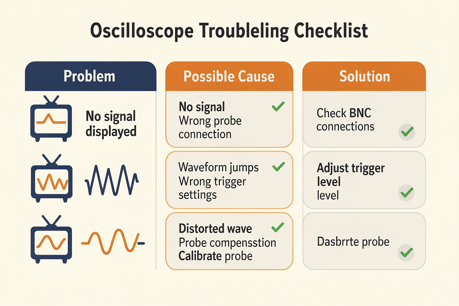
Even beginners face challenges when starting with oscilloscopes. Here's a quick troubleshooting guide:
| Problem | Possible Cause | Solution |
|---|---|---|
| No signal displayed | Wrong probe connection | Check BNC connections |
| Waveform jumps around | Wrong trigger settings | Adjust trigger level |
| Vertical/Horizontal scale wrong | Incorrect V/div or time/div | Verify settings |
| Waveform distorted | Probe compensation |
Ready to start building?
Explore our collection of DIY kits and components. All project components mentioned in this blog are available in our store.
Browse All Projects