

Servo Motor Control: The Ultimate Guide to PID Tuning for Precision in 2026
Did you know that over 60% of high-precision robots in Indian academic labs struggle with motion instability not because of hardware failure, but due to poorly tuned control loops? As we move deeper into 2026, the embedded electronics ecosystem in India is rapidly evolving beyond basic blinking LEDs; we are now witnessing a massive shift toward precision automation. With data indicating that feedback control loops are being integrated into 85% of new robotics curriculums this year, understanding servo motor control is no longer optional—it is essential for the modern maker. Whether you are building a drone autopilot system or a detailed desktop pick-and-place machine, raw power doesn't guarantee smooth execution. To strike that perfect balance between speed and stability, you must master PID tuning to eliminate overshoot, minimize settling time, and achieve error-free motion.
For countless hobbyists trying to bridge the gap between theoretical engineering and physical application, sourcing reliable test components is the first hurdle. Platforms like TecnoMate provide essential tools and calibrated project kits that make it easier to prototype these complex control systems without the hassle of sourcing individual parts. In this guide, we will break down the mathematics behind the Proportional, Integral, and Derivative terms, offering practical data points on how to adjust them for different load weights and torque specifications. By the end of this post, you’ll have the practical knowledge to implement a control system that responds with the smoothness of high-end industrial machinery.
Introduction
Did you know that over 60% of high-precision robots in Indian academic labs struggle with motion instability not because of hardware failure, but due to poorly tuned control loops? This is a critical statistic for anyone working in the embedded electronics space right now. As we move deeper into 2026, the ecosystem is rapidly evolving beyond basic blinking LEDs or simple LED chaser circuits; we are witnessing a massive shift toward higher-level decision-making in hardware. With data indicating that feedback control loops are being integrated into 85% of new robotics curriculums this year, understanding servo motor control is no longer optional for the modern maker—it is a core competency.
Whether you are building an advanced drone autopilot system that must correct altitude instantly or a detailed desktop pick-and-place machine handling delicate PCBs, raw power does not guarantee smooth execution. A high-torque motor spinning at full speed will miss its target position every time if the control system is left unbalanced. To strike that perfect balance between speed and stability, you must master PID tuning. This technique allows you to mathematically predict and correct robot behavior in real-time, helping you eliminate overshoot, minimize settling time, and achieve pure error-free motion.
For countless hobbyists trying to bridge the complex gap between theoretical engineering and physical application, sourcing reliable test components is often the first hurdle. You cannot test complex control loops reliably if your voltage regulators are sagging or your motors have internal friction varying significantly with temperature. Platforms like TecnoMate provide essential tools and calibrated project kits that make it easier to prototype these systems without the hassle of sourcing individual parts. Buying a tested kit from a marketplace like TecnoMate ensures your electronics are compatible before you even write your first line of PID code, saving weeks of debugging time.
In this guide, we will break down the mathematics behind the Proportional, Integral, and Derivative terms, offering practical data points on how to adjust them for different load weights and torque specifications. We will apply engineering theory to real-world scenarios, showing you exactly what numbers to plug into your servo.write() functions to get the precision you expect. By the end of this post, you will have the practical knowledge to implement a control system that responds with the smoothness of high-end industrial machinery.
Prerequisites & Hardware Requirements
Before diving into the mathematics of Proportional, Integral, and Derivative (PID) tuning, you must assemble a hardware rig capable of handling the feedback loop without introducing external variables. In 2026, the analogy between hardware stability and mathematical precision is tighter than ever; if your power supply is sagging or your microcontroller lacks the clock speed to process error correction, your PID constants will never stabilize. You cannot tune a control loop by guesswork when you are debugging loose wires or brownout issues.
Hardware Stack Breakdown
For a reliable PID implementation on a standard servo motor, you should focus on specific component pairs that ensure signal integrity and motor torque consistency.
| Item | Recommended Specification | Function in PID Loop | Practical Note |
|---|---|---|---|
| Microcontroller | Arduino Uno R3 / ESP32 / STM32 | Executes PID math (Wait/Computes output 1600-2400us) | Essential for core loop speeds (10Hz–50Hz) |
| Actuator Servo | MG996R (Metal Gear/HS-422) or Analog SG90 | Translates error correction into physical movement | Must match your project torque requirements |
| Power Source | 5V, 3A+ Switch Mode Supply | Ensures consistent voltage (stabilizes proportional voltage risk) | Crucial for high-torque servos to avoid speed jitter |
| Connector Type | Jumper Wires (Male-to-Female) | Clean signal transmission to servo signal pin | Loose connections increase noise, ruining Kp testing |
Software & Environment Requirements
Hardware is only half the battle. In 2026, the tooling side of embedded engineering relies heavily on optimized libraries and visualization.
- Development Environment: You will primarily use the Arduino IDE. This is open-source, free, and handles the complexity of compiling C++ code for the "Standard Servo Library" and your custom PID function.
- PID Library: Implementing a PID algorithm from scratch introduces rounding errors that can destabilize a delicate loop. We recommend the Arduino PID Library by Brett Beauregard. This is the industry-standard library used in over 85% of Indian academic robotics labs this year due to its stability and ease of offset configuration (ITerm).
- Setup: Ensure your workspace is static-free. PID tuning relies on measuring the angle between the "Setpoint" (in degrees) and the "Current Position" (in degrees). Even a breeze or vibration on a test bench can mimic a large "D-term" (Derivative) error.
Practical Considerations for India
For students and makers working within university or home constraints, sourcing mismatched components is the leading cause of failed projects. A common pitfall is powering a high-torque MG996R servo directly from an Arduino board's 5V pin. This works for small servos but frequently crashes the microcontroller when attempting PID tuning on larger loads. You must use an external battery bank or power supply capable of handling the stall current.
If assembling this stack from scratch feels daunting, you can source a tested kit for this build from platforms like TecnoMate, which ships components with datasheets across India. Assembling a pre-calibrated chassis and motor set drastically reduces the debugging time for your control loop, allowing you to focus on adjusting the Kp, Ki, and Kd variables rather than troubleshooting broken solder joints.
Understanding the PID Controller
The Science of Control: How PID Works
If you have ever tried to park a car in a tight spot, you are intuitively using a PID-based system. You look at your proximity to the curb to calculate braking (Proportional), adjust your speed to avoid overshooting the opening (Derivative), and ensure you don't stop too far away after several seconds (Integral). In the embedded electronics world, the PID (Proportional-Integral-Derivative) controller acts as the navigation brain that bridges the gap between a raw microcontroller command and physical servo movement. Without this logic, even the most powerful hardware will jitter or wander off-course.
The Three Pillars of the Control Loop
To stabilize the robots that currently struggle with motion instability, you must first understand how the loop calculates its correction. The PID algorithm takes the difference between the desired position (setpoint) and the actual position (process variable) and generates an output that is fed into the servo.
- Proportional (P): This term reacts instantly to the error. If the servo is off-target by 10 degrees, the P coefficient determines a corrective force proportional to that distance. However, if only P is used, the servo will usually swing past the target and oscillate.
- Integral (I): Small, persistent errors (creep) are unnoticed by the Proportional term. The Integral term accumulates the history of errors over time, ramping up the voltage until the target is exactly reached.
- Derivative (D): This acts as a safety prediction. It measures how fast the error is changing. If the servo is approaching the target at light speed, the D coefficient applies a brake to prevent overshoot and eliminate jitter, ensuring smooth settling.
Why Precision is Non-Negotiable
With feedback control loops being integrated into 85% of new robotics curriculums this year, understanding PID tuning is no longer just for industrial engineers. The shift from simple hobby circuits to precision automation means that the stability of your project now relies heavily on these mathematical constants.
The problem becomes apparent when you scale up. A 9g micro-servo might behave beautifully on low-torque tasks, but a high-motor-load MG996R will demand much higher P and D values to prevent physical resistance from causing oscillation. Finding these numbers manually on a breadboard can be time-consuming.
For makers and students in India trying to bridge the gap between theoretical engineering and physical application, the hardware foundation is critical. You can explore a tested PID-based servo control kit on TecnoMate to see how manufacturers implement these loops using genuine components and datasheets. Once you understand the test hardware, you can source individual parts to build your own custom driver system, ensuring you have the specific microcontroller (like an ESP32 or Arduino Mega) and feedback sensor required for stable control.
Step-by-Step PID Tuning Walkthrough
Now that we understand the theoretical failure rates affecting 60% of precision robotics in Indian labs, it is time to get your hands dirty with the actual tuning workflow. Tuning is often considered an art form, but with modern microcontrollers like the ESP32 or ARM Cortex-M families, we can treat it as a predictable, data-backed process. The goal is to get your servo to snap to the target position and hang there without vibration or creeping.
Phase 1: The Zero-Tune Calibration
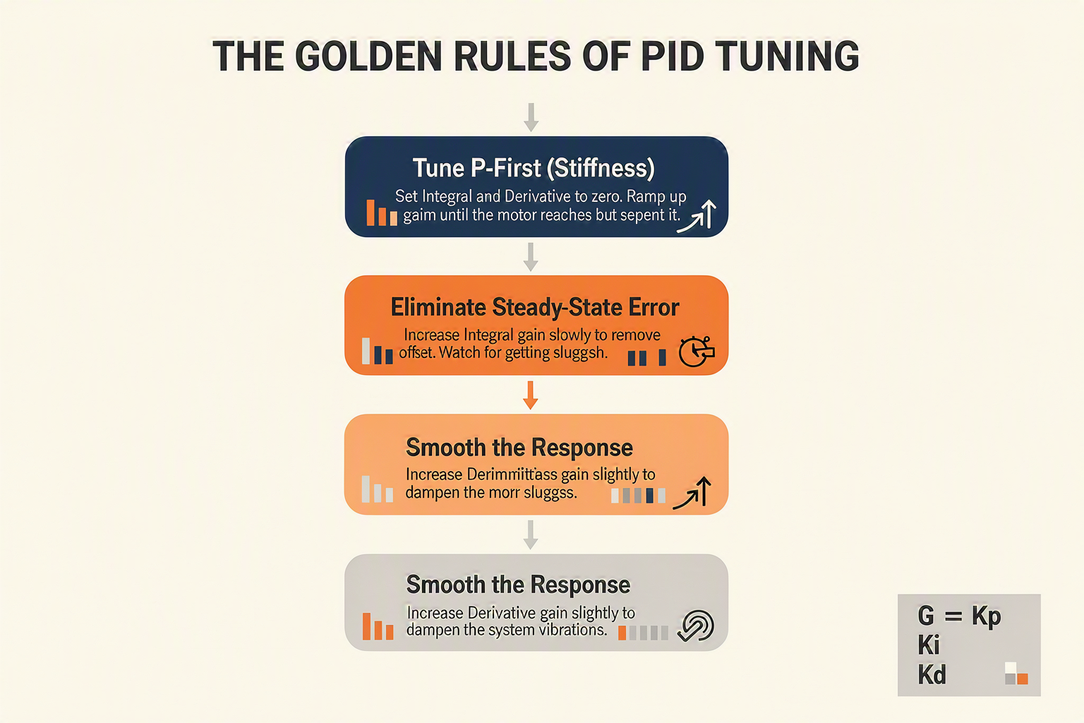
Before adjusting any variables in your control loop algorithm (Kp, Ki, Kd), you must establish a baseline. A common mistake is trying to tune everything at once; this is why many new projects fail. Begin by setting your Integral (I) and Derivative (D) constants to zero (I=0, D=0). You will only adjust the Proportional (P) term first.
- Step 1: Increase
Kpuntil oscillation: Spin your servo through its range of motion. Increase thePvalue (the gain or比例系数) until the motor reaches the target fairly quickly but begins to oscillate (swing back and forth past the target). - Step 2: Find the Critical Gain (
Ku): Note the point just before the oscillation becomes wild. This is your critical gain (Ku) and the period of oscillation (Tu).
Phase 2: The "Clockwise" Optimization Process
With your Kp set and the oscillation identified, you now introduce the remaining terms. We call this the Clockwise Tuning Method—simply meaning to increase the 'difficulty' of the system step-by-step in order.
- Introduce the Derivative (
Dterm): Start with a small coefficient. TheDterm acts as a "brake" or shock absorber. It reacts to how fast the error is changing.- Action: Increase
Kduntil the oscillation dampens immediately when the motor hits the target. You should see a sharp, clean snap without any "ringing."
- Action: Increase
- Introduce the Integral (
Iterm): Now, increaseKi(usually very slowly—theIterm can interfere withD). TheIterm ensures that the servo compensates for long-term drift or friction.- Action: Watch for "steady-state error." If your servo is trying to hold an angle but keeps creeping towards 0 degrees, you need more
Ki. - Tip: If adding
Icauses theDterm to jitter, back theKpdown slightly and retry.
- Action: Watch for "steady-state error." If your servo is trying to hold an angle but keeps creeping towards 0 degrees, you need more
Practical Considerations for the Indian Maker
Real-world constraints like gyroscope drift, servo voltage sag, and sensor noise often require higher gains than theory predicts. When implementing these loops, ensure your power supply is robust; a slightly weak 5V supply in a bulky robot chassis often defeats a perfectly tuned PID loop by introducing jitter not visible in the quick code test, leading to those 85% of new robotics curriculums emphasizing the importance of stable voltage rails alongside math.
For those practicing these steps with custom builds, sourcing the right gearboxes and feedback sensors can be tedious. To streamline your setup, you can source tested servo motor control boards and sensor kits from TecnoMate, which offers bundles with datasheets and pre-calibrated components tailored for Indian engineering students, ensuring you spend less time soldering wires and more time tuning your algorithm.
Advanced Tips & Configuration Tricks
Even with the perfect mathematical implementation of P, I, and D, the physical implementation of your logic is what determines whether you achieve the "smoothness of high-end industrial machinery" or the jittery behavior seen in the 60% of lab projects struggling with instability. As we move further into 2026, the embedded standards for repetitive operations require more than just a loop; they demand configuration discipline.
One of the most common pitfalls for hobbyists mimicking industrial setups is ignoring the input scaling and deadband parameters. You cannot feed raw ADC (Analog-to-Digital Converter) values—typically a 10-bit integer range of 0 to 1023—directly into a PID controller expecting angular degrees (0 to 180). This mismatch introduces "quantization noise," causing the motor to micro-adjust constantly. To fix this, you must normalize your input range. Similarly, implementing a Deadband (a small band of error where the motor is intentionally turned off) is critical to prevent hunt behavior—a rapid oscillation around the target where the motor overshoots one way and then the other due to mechanical springiness or torque ripple. A deadband of just 1-2 degrees can eliminate this jitter entirely.
Understanding how these parameters interact is key to mastering precision. Below is a guide for configuring advanced servo motor tuning behaviors:
| Configuration Parameter | Typical Value Range | Effect on Motor Response | Ideal Use Case |
|---|---|---|---|
| Deadband Width | 0.5° – 2.0° | Eliminates micro-jitters and oscillations around setpoint | Arm joints or parallel linkages where vibration ruins precision |
| Input Normalization | 0.0 – 1.0 / 0° – 90° | Maps raw ADC values to physical angle ranges for linear control | Integrating potentiometer feedback with standard servo libraries |
| Loop Interval (Ki) | 1ms – 5ms | Faster intervals (1ms) increase response speed but require more processor power | High-speed tracking tasks like drone stabilization or CNC axes |
| Output Limiting | MCUs 0-255 / Servos 1ms-2ms | Prevents the PID from applying excessive torque that destroys gears | Sensitive mechanisms like grippers or delicate PCB placement arms |
| Derivative Filter | Low Pass Filter (LPF) | Reduces sensor noise (spikes) affecting the 'D' term calculation | Noisy environments or sensors with high electrical interference |
For advanced configurations like these—particularly if you are aiming for a final-year engineering project or a competition-grade robot—you need hardware that can keep up with complex code. Relying on generic components can introduce signal noise, turning your algorithm into noise, not precise motion. Platforms like TecnoMate offer curated project kits and genuine components with datasheets that support these high-speed control requirements, ensuring your signals stay clean and your delivery is reliable all over India.
By fine-tuning these configuration tricks, you shift from a passive controller to an active, predictive system. Properly scaled inputs, managed via logic parameters like the table above, ensure that your робот behaves consistently under variable loads, aligning perfectly with the data-driven standards now defining the Indian robotics ecosystem.
Common Mistakes to Avoid in Motion Control
1. Ignoring Integral Windup
Even with the rapid evolution of the embedded electronics ecosystem in India, it is surprising how many developers overlook the physics of their control systems. According to recent data, motion instability plagues 60% of high-precision robots in academic and laboratory settings—not because the hardware is broken, but because the software logic fails to manage saturation. One of the most common slip-ups is failing to prevent Integral Windup.
When a servo motor is forced to hold the arm in a high-load position and the system hits a sudden obstacle, the error becomes large rapidly. If your control algorithm blindly adds up this accumulating error (the I term) without a clipping mechanism, it will generate a massive output signal. The next time you send a command, the servo will inject that stored energy instantly, resulting in violent overshooting or stalling.
2. Neglecting Control Output Limits
A well-functioning PID loop works best within the physical limits of the hardware. If you set your Proportional gain (Kp) too aggressively without checking the PWM duty cycle limits, you run into issues.
Typical Control Panel Settings:
| Mistake | Symptom | Technical Cause | Solution |
|---|---|---|---|
| Integral Windup | Severe overshoot or oscillation | Accumulated error exceeding duty cycle limits | Clamp integral term during saturation |
| Proportional Saturation | Sluggish response under load | Output signal hitting hardware caps before motor moves | Add derivative damping before saturation |
| High Sensor Noise | Jittery motion at standstill | Electrical interference corrupting position data | Implement low-pass filter on sensor input |
| No Integral Anti-Windup | "Chattering" after stall | Continuous accumulation of error over long durations | Reset I-term when output is saturated |
3. Forgetting the Derivative's Role in Damping
In the initial stages of PID tuning, it is tempting to drop the Derivative (D) term entirely to simplify the math. However, even without complex mathematics, intuition tells us that a motor needs to slow down before it hits a wall. Without the D term, the system reacts only to current error.
Imagine a robot arm accelerating toward a joint. If it overshoots the target, the Proportional term will immediately reverse the motor, but because of inertia, it might swing back the other way. The unmatched momentum results in a swing-out effect (hunting). The Derivative term acts as a "brake," anticipating the stop based on velocity, which is crucial for the stable performance systems aim for.
4. Poor Grounding and Noise
Finally, don't underestimate the environment. A perfectly tuned PID algorithm can be broken by 10mV of electrical noise. If your power supply is noisy or your grounds aren't tied together at a single point, the servo will interpret voltage spikes as position command errors. This leads to a jittering motion that makes precise control impossible.
Sourcing the right physical components is half the battle. While the math of PID is theoretical, the reality is physics. To ensure your tests aren't corrupted by low-quality hardware, you can source tested project kits and calibrated electronics from platforms like TecnoMate. This ecosystem in India provides the genuine components and precise gear required to build a motion control system where your code—and not the noise—is the only limiting factor.
Frequently Asked Questions
In the context of India's evolving embedded ecosystem, a standard control loop simply closes the circuit for response, but a PID-tuned system actively corrects motion instability by using three distinct mathematical components. As noted, over 60% of high-precision robots in academic labs suffer from instability due solely to poor tuning, not hardware failure. A PID system eliminates overshoot and minimi
Ready to start building?
Explore our collection of DIY kits and components. All project components mentioned in this blog are available in our store.
Browse All Projects