

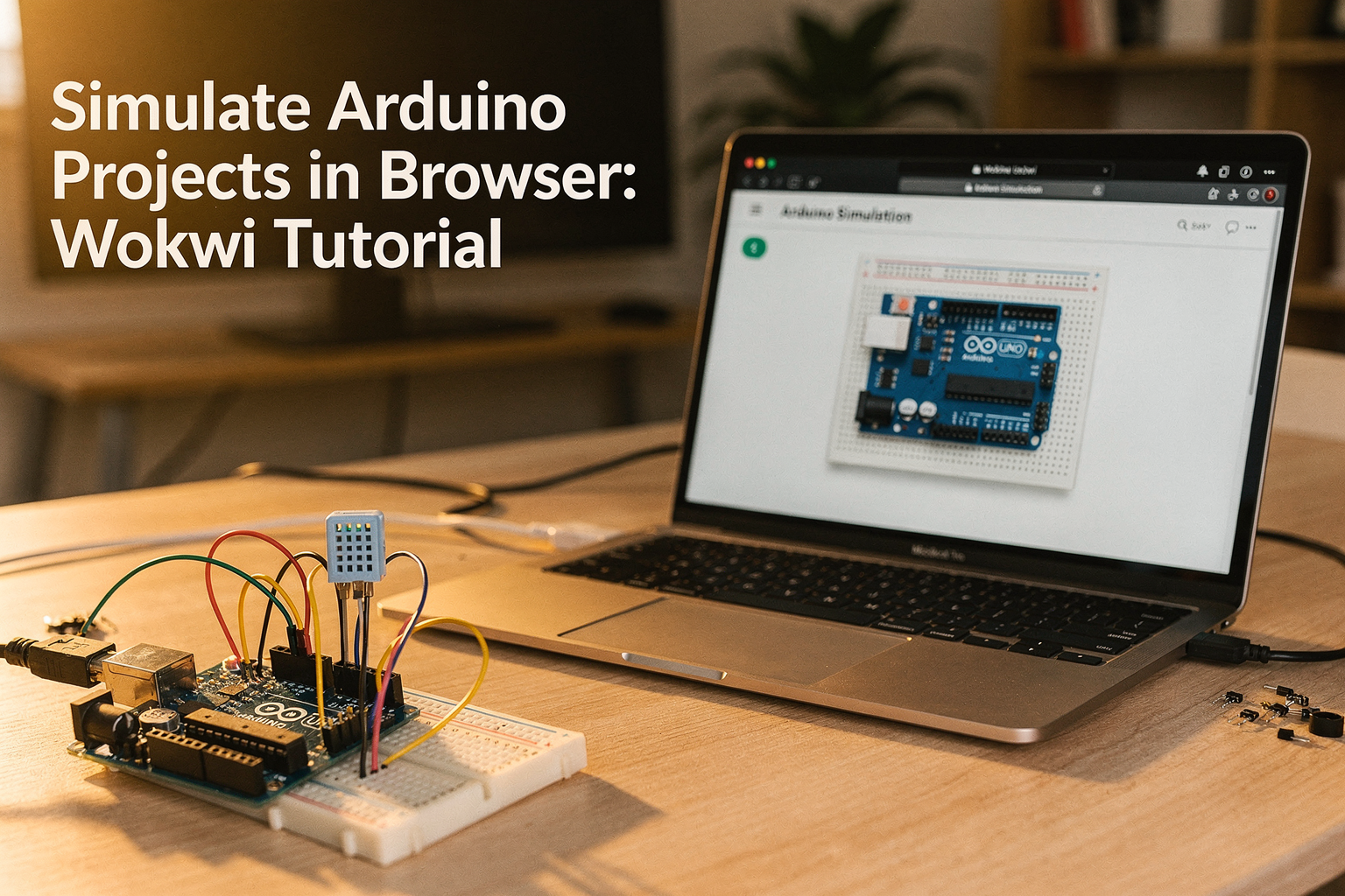
Introduction
Imagine building and testing your Arduino projects without spending a single rupee on components! What if you could debug your code instantly, experiment with different components, and perfect your designs before investing in hardware? Welcome to the world of simulation - where your imagination meets reality without the cost barrier.
For Indian engineering students and DIY enthusiasts, this isn't just a convenience; it's a game-changer. With the rising costs of electronic components and the pressure to complete semester projects efficiently, simulating Arduino projects in your browser using Wokwi offers the perfect solution. This powerful tool lets you write code, connect virtual components, and see real-time results - all from your web browser!
In this comprehensive tutorial, we'll explore how to harness the power of Wokwi to simulate Arduino projects, from beginner-friendly LED circuits to complex IoT systems. By the end, you'll have the confidence to tackle any Arduino project, knowing you can test and perfect it virtually first.
Why Simulate Arduino Projects in Your Browser?
The Indian Engineering Student Advantage
As an engineering student in India, you're constantly balancing theoretical knowledge with practical implementation. Traditional learning often involves purchasing components for each project, which can quickly deplete your limited budget. However, simulation tools like Wokwi bridge this gap by providing:
- Cost-free experimentation: No need to buy components for every idea
- Instant feedback: Debug in real-time without hardware delays
- Component availability: Access to rare components you might not find locally
- Batch testing: Run multiple scenarios quickly
- Portfolio building: Create impressive project demonstrations
Real-World Applications for Indian Students
The simulation approach isn't just academic - it mirrors professional engineering practices. Companies worldwide use simulation tools for prototyping before physical implementation. By learning these skills, you're aligning your education with industry standards, making you more employable in India's growing electronics sector.
Getting Started with Wokwi
Account Setup and Interface Overview
Getting started with Wokwi is incredibly simple:
- Visit wokwi.com on your browser
- Click "Sign Up" and create your free account
- No installation required - everything runs in your browser!
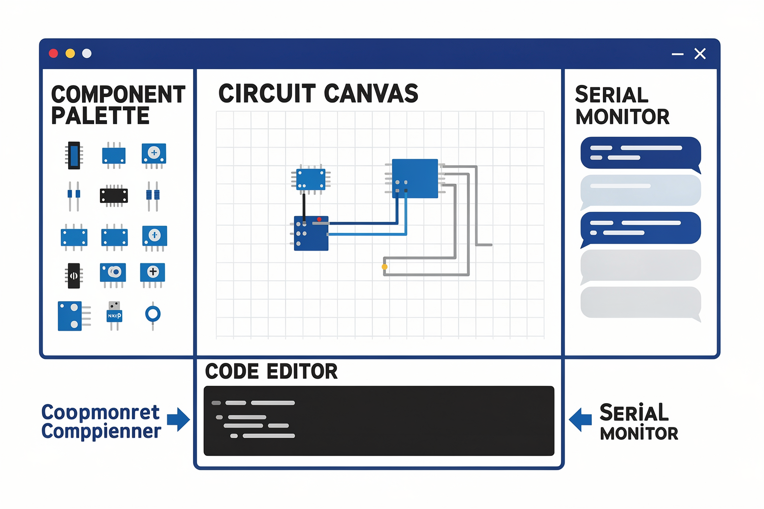
The Wokwi interface is intuitive and beginner-friendly:
- Left Panel: Component palette with drag-and-drop functionality
- Center Area: Circuit canvas for visual circuit design
- Bottom Panel: Code editor with Arduino IDE-like interface
- Right Panel: Serial monitor and output display
Browser Requirements
Wokwi works on any modern browser:
- Chrome, Firefox, or Safari (latest versions)
- Mobile browser support for quick prototyping
- No additional plugins or extensions needed
Your First Arduino Simulation: LED Blink
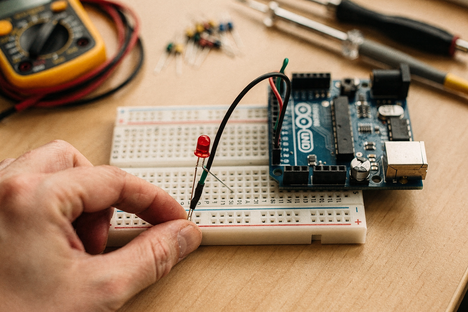
Let's start with the classic "Hello World" of Arduino projects - the LED blinker. This will help you understand the basic workflow of simulation.
Step-by-Step Guide
Step 1: Create a New Project
- Click "New Project" on the dashboard
- Give it a name like "My First Blink"
Step 2: Add Components
- From the component palette, drag an Arduino Uno
- Add an LED (use the round component)
- Add a 330Ω resistor (next to the LED)
- Drag a breadboard to connect everything
Step 3: Design the Circuit
- Connect the LED's longer leg (anode) to pin 13 of Arduino
- Connect the shorter leg (cathode) to one end of the resistor
- Connect the other end of the resistor to GND
- Ensure Arduino's 5V and GND are connected to the breadboard rails
Step 4: Write the Code Replace the default code with:
void setup() {
  // Initialize pin 13 as an output
  pinMode(13, OUTPUT);
}

void loop() {
  // Turn LED on (HIGH is voltage level)
  digitalWrite(13, HIGH);

  // Wait for 1 second
  delay(1000);

  // Turn LED off by making the voltage LOW
  digitalWrite(13, LOW);

  // Wait for 0.5 seconds
  delay(500);
}
Step 5: Run and Observe
- Click "Start Simulation" (green play button)
- Watch the LED on screen blink every 1.5 seconds
- Open the serial monitor to verify code execution
Visual Feedback and Debugging
Notice how Wokwi shows real voltage levels and current flow. This visual feedback is invaluable for understanding circuit behavior - something you can't get from standalone code editors!
Components Required for Advanced Projects
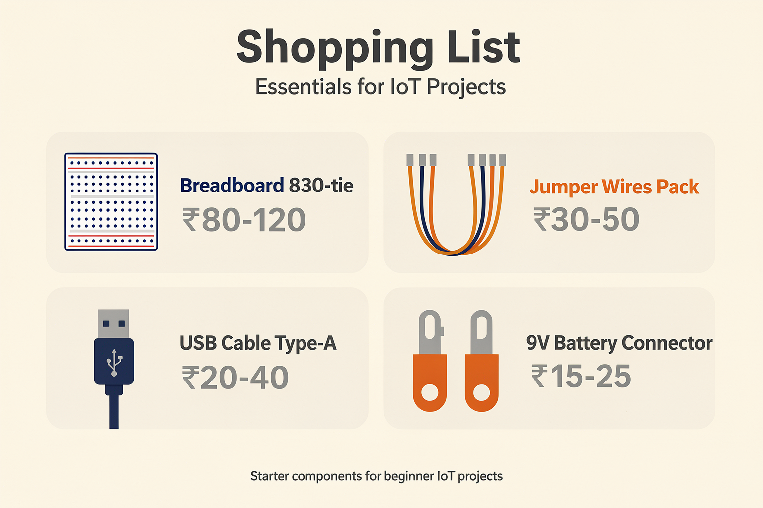
While the LED blinker uses basic components, real-world projects require a diverse toolkit. Here's a comprehensive component list with Indian market pricing:
Essential Components Table
| Component | Specification | Price (₹) | Common Uses |
|---|---|---|---|
| Arduino Uno | ATmega328P, 14 Digital I/O | 450-600 | All Arduino projects |
| ESP32 | WiFi + Bluetooth, 24 GPIO | 450-550 | IoT projects, WiFi apps |
| DHT22 | Temperature & Humidity | 150-200 | Weather monitoring |
| Ultrasonic Sensor HC-SR04 | 2cm-400cm range | 150-200 | Distance measurement |
| Servo Motor SG90 | 180° rotation, 1.8kgcm | 120-150 | Robotics, automation |
| Stepper Motor NEMA 17 | 1.8° step angle | 400-550 | Precision positioning |
| Relay Module | 5V/12V, 10A switching | 100-150 | High voltage control |
| LCD 16x2 | I2C interface | 80-120 | User interface |
| Buzzer Passive | 2-5V, 200-400Hz | 20-30 | Audio alerts |
| Push Button Tactile | 6x6x18mm | 5-10 | User input |
Power Supply Components
| Component | Specification | Price (₹) | Notes |
|---|---|---|---|
| Breadboard 830-tie | 830 points, 77mm × 55mm | 80-120 | Essential for prototyping |
| Jumper Wires Pack | 40pcs male-to-male | 30-50 | Multiple colors recommended |
| USB Cable Type-A | 1.5m standard length | 20-40 | For Arduino power |
| 9V Battery Connector | Terminal block type | 15-25 | For portable projects |
Advanced Simulation: Multi-Component IoT Weather Station
Let's build something more complex that showcases the power of simulation. We'll create a weather station that displays temperature and humidity.
Circuit Design with Multiple Components
Components Used:
- ESP32 (WiFi enabled microcontroller)
- DHT22 sensor for temperature/humidity
- OLED Display (128x64 I2C)
- Buzzer for alerts
- Push button for manual readings
Connection Diagram:
ESP32 → DHT22 (Pin 4)
ESP32 → OLED (SDA: Pin 21, SCL: Pin 22)
ESP32 → Buzzer (Pin 18)
ESP32 → Push Button (Pin 19 with pull-up resistor)
Complete Project Code
#include <DHT.h>
#include <Wire.h>
#include <Adafruit_GFX.h>
#include <Adafruit_SSD1306.h>

// Pin definitions
#define DHT
Ready to start building?
Explore our collection of DIY kits and components. All project components mentioned in this blog are available in our store.
Browse All Projects