

Introduction
Solar energy monitoring is becoming increasingly important in India as we move towards sustainable energy solutions. Whether you're a hobbyist looking to track your home solar setup or an engineering student working on a renewable energy project, understanding how to monitor solar panel performance is a valuable skill. In this comprehensive guide, we'll walk you through building a solar panel monitoring system using Arduino and an IoT dashboard, perfect for projects in Indian conditions.
Solar panel monitoring helps you track power generation, identify issues, and optimize performance. With the rising cost of electricity bills in India and the government's push for solar adoption, having a DIY monitoring solution can save you thousands of rupees annually. Plus, it's an excellent learning project that combines hardware interfacing, programming, and IoT technology.
Components Required
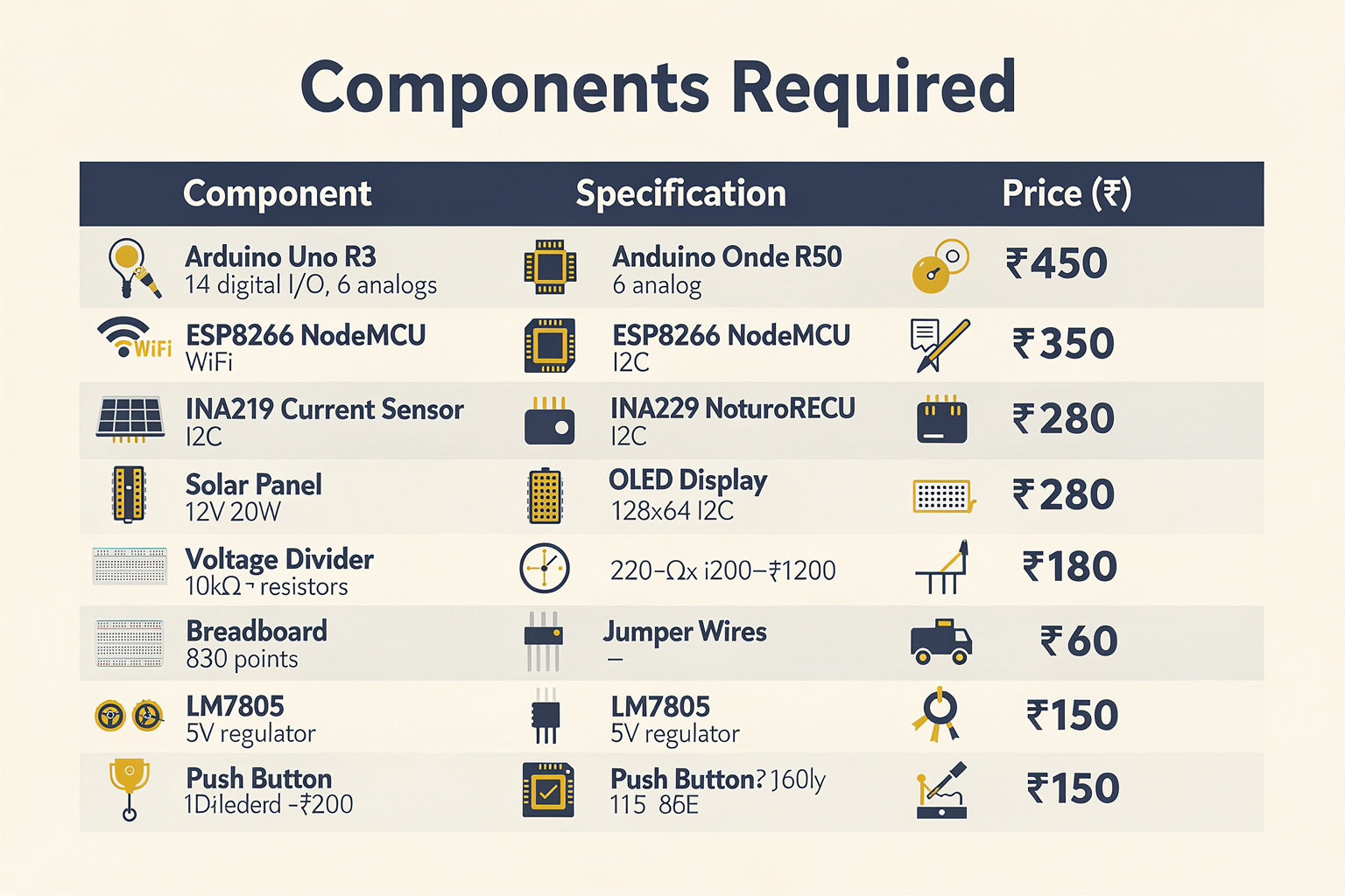
Before we dive into the technical details, let's gather all the necessary components. Most of these are readily available at your local electronics markets in India, including Lamington Road in Mumbai, SP Road in Bangalore, or Chandni Chowk in Delhi.
| Component | Specification | Price (₹) | Where to Buy |
|---|---|---|---|
| Arduino Uno R3 | 14 digital I/O, 6 analog | 450 | Local electronics stores |
| ESP8266 NodeMCU | WiFi enabled, 3.3V | 350 | Online: Amazon.in, Flipkart |
| INA219 Current Sensor | DC current monitoring | 280 | Local electronics markets |
| Solar Panel | 12V, 20W (for testing) | 800-1200 | Solar suppliers |
| Voltage Divider | 10kΩ/10kΩ resistors | 20 | Electronics shops |
| OLED Display (128x64) | I2C interface | 180 | Online: Robokits India |
| Breadboard | 830 tie-points | 80 | Local electronics markets |
| Jumper Wires | Male to male, etc. | 60 | Electronics shops |
| 5V Voltage Regulator | LM7805 | 15 | Local electronics stores |
| Push Button | Momentary | 10 | Electronics shops |
| Capacitors (100µF, 0.1µF) | Electrolytic | 30 | Local electronics markets |
Total estimated cost: ₹2,355
Note: Prices are approximate and may vary based on location and supplier. Check with local vendors on Lamington Road or SP Road for the best deals.
Understanding Solar Panel Monitoring
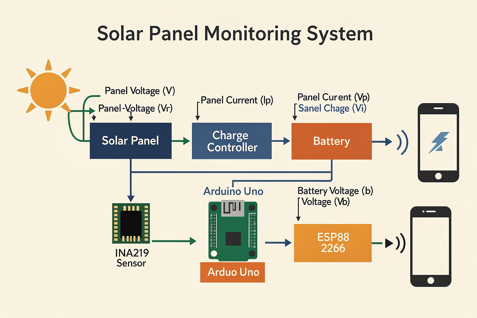
Before we start building, let's understand what we're monitoring. A typical solar panel setup includes:
- Solar Panel: Converts sunlight into DC electricity
- Charge Controller: Regulates the voltage and current
- Battery: Stores excess energy
- Inverter: Converts DC to AC (if needed)
Our monitoring system will focus on measuring:
- Panel voltage (Vp)
- Panel current (Ip)
- Battery voltage (Vb)
- Power output (P = V × I)
- Energy generated (kWh)
The INA219 sensor is perfect for this application as it can measure both voltage and current using I2C communication, making it ideal for Arduino projects.
Circuit Setup and Wiring
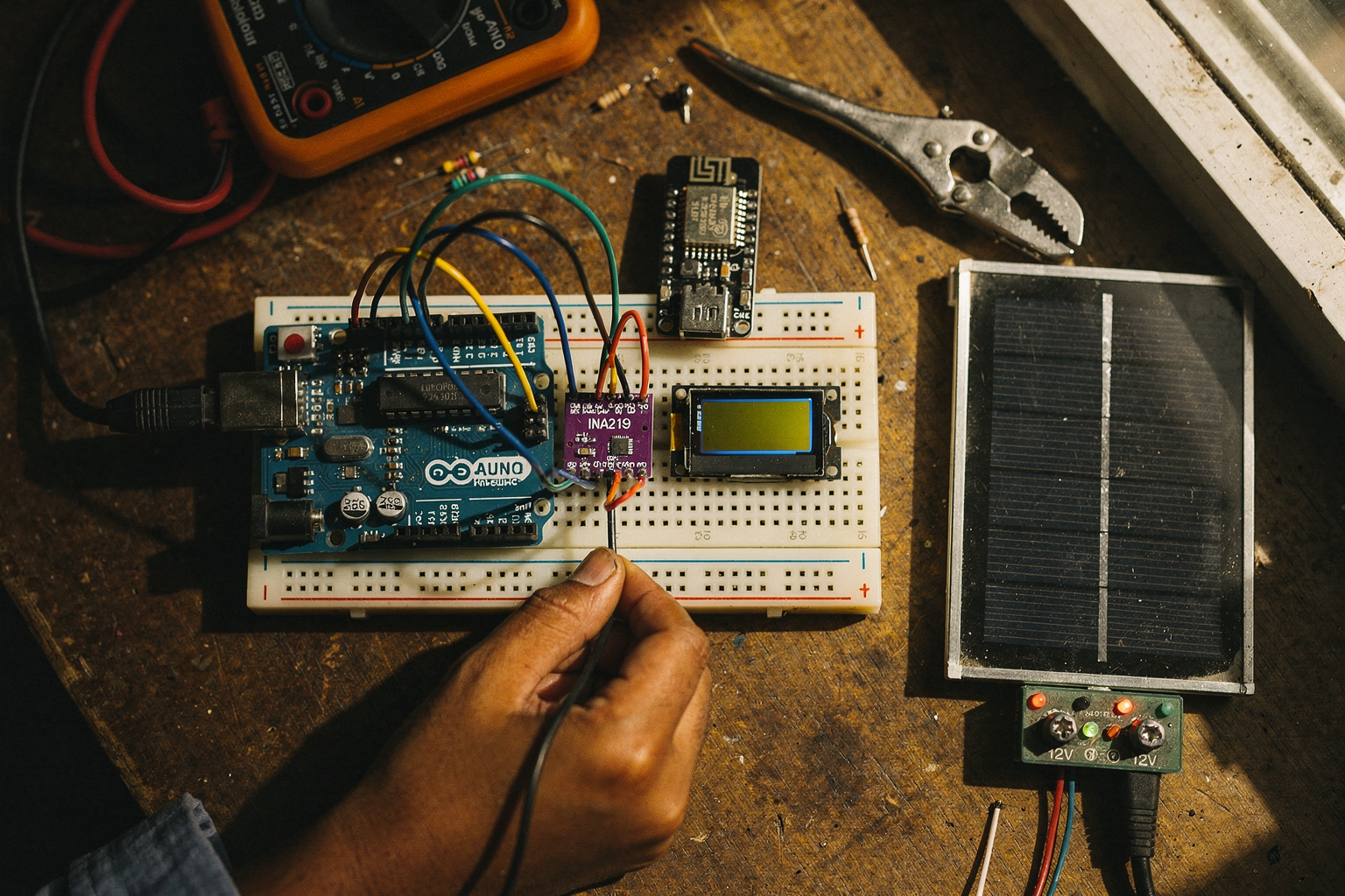
Let's set up our circuit step by step. The circuit diagram is simple but crucial for accurate readings.
[Solar Panel] --> [Charge Controller] --> [Battery]
            |
            v
        [INA219 Sensor] --> Arduino
            |
            v
        [ESP8266 NodeMCU] --> WiFi
            |
            v
        [OLED Display] --> Local Display
Step-by-Step Wiring:
-
INA219 Sensor to Arduino Uno:
- SDA pin → A4 (Arduino Uno)
- SCL pin → A5 (Arduino Uno)
- VCC → 5V
- GND → GND
-
ESP8266 NodeMCU Setup:
- Connect to Arduino via USB for programming
- Configure WiFi credentials in code
-
OLED Display Connection:
- SDA → A4
- SCL → A5
- VCC → 5V
- GND → GND
-
Power Connections:
- Solar panel → Charge controller → Battery
- Use appropriate gauge wires for current flow
- Add fuses for safety (2-3A rating)
Important Safety Notes:
- Always work with solar panels in shade while wiring
- Use proper insulation for all connections
- Keep soldering iron away from active solar panels
- Double-check polarity before connecting
Step-by-Step Arduino Programming
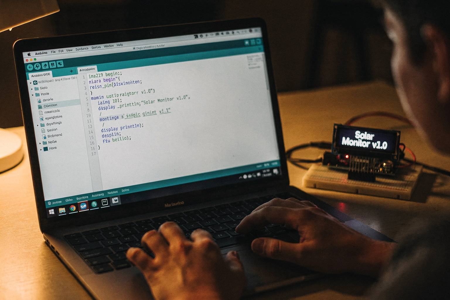
Now let's write the code for our Arduino. We'll use the Adafruit INA219 library for accurate measurements.
Installing Required Libraries:
- Open Arduino IDE (version 1.8.19 or higher)
- Go to Tools → Manage Libraries
- Search for and install:
- Adafruit INA219 Library by Adafruit
- Adafruit Unified Sensor
- SPI library (usually pre-installed)
Complete Arduino Code:
#include <Wire.h>
#include <Adafruit_INA219.h>
#include <Adafruit_Sensor.h>
#include <Adafruit_GFX.h>
#include <Adafruit_SSD1306.h>

// Initialize INA219 sensor
Adafruit_INA219 ina219;

// Initialize OLED display
#define OLED_RESET 4
Adafruit_SSD1306 display(128, 64, &Wire, OLED_RESET);

// WiFi credentials for ESP8266
const char* ssid = "YourWiFiName";
const char* password = "YourWiFiPassword";

// Global variables
float panelVoltage = 0;
float panelCurrent = 0;
float batteryVoltage = 0;
float power = 0;
float shuntVoltage = 0;
float busVoltage = 0;
float maxPower = 0;
float energyToday = 0;
unsigned long previousMillis = 0;
const long interval = 2000; // Update every 2 seconds

void setup() {
  Serial.begin(115200);

  // Initialize OLED display
  if(!display.begin(SSD1306_SWITCHCAPVCC, 0x3C)) {
    Serial.println(F("SSD1306 allocation failed"));
    for(;;);
  }

  // Initialize INA219 sensor
  if(!ina219.begin()) {
    Serial.println(F("Failed to find INA219 chip"));
    Serial.println(F("Check your wiring!"));
    for(;;);
  }

  // Configure INA219 for solar monitoring
  ina219.setCalibration_32V_2A();
  ina219.setCalibration_32V_1A();
  ina219.setCalibration_16V_1A();
  ina219.setCalibration_8V_0_1A();

  // Set shunt and bus resistor values (typical solar setup)
  ina219.setShuntResistance(0.1); // 0.1Ω shunt resistor
  ina219.setBusVoltageRange(32); // 32V max (adjust based on your setup)

  display.clearDisplay();
  display.setTextSize(1);
  display.setTextColor(WHITE);
  display.setCursor(0, 0);
  display.println("Solar Monitor v1.0");
  display.println("Initializing...");
  display.display();

  delay(2000);
}

void loop() {
  unsigned long currentMillis = millis();

  // Calculate sensor readings every interval
  if(currentMillis - previousMillis >= interval) {
    previousMillis = current
Ready to start building?
Explore our collection of DIY kits and components. All project components mentioned in this blog are available in our store.
Browse All Projects