Arduino Relay Shield 4-Channel – 5V 10A SPDT Relay Module for Arduino UNO & Mega
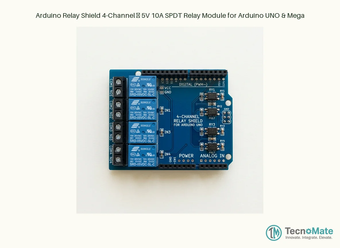
The Arduino 4-Channel Relay Shield is a plug-and-play expansion board that lets you safely control high-voltage and high-current AC or DC loads directly from your Arduino UNO, Mega, or compatible board. Instead of struggling with loose relay modules, jumper wires, and breadboards, this shield stacks neatly on top of your Arduino—no extra wiring needed.
Each of the four independent relays is an SPDT (Single Pole Double Throw) type, providing both Normally Open (NO) and Normally Closed (NC) contacts on easy-to-use screw terminals. Rated for up to 10A at 250VAC or 10A at 30VDC, a single shield can switch lights, fans, pumps, solenoid valves, door locks, or even small motors. Four bright LED indicators show at a glance which relays are energized, making debugging and prototyping faster.
Built with optocoupler isolation and relay driver circuitry on-board, the shield protects your Arduino's sensitive I/O pins from voltage spikes and back-EMF. The relays are mapped to specific Arduino pins (typically D4, D7, D8, D12), leaving other I/O pins free for sensors, displays, or communication modules. The standard Arduino R3 header footprint ensures compatibility with UNO R3, Mega 2560, and most Arduino-compatible boards.
Whether you're building a home-automation system, an IoT smart switch, an incubator controller, or a robotics project, this relay shield gives you reliable, high-power switching in a compact, hassle-free package. It's one of the most popular shields in the Indian maker ecosystem—trusted by engineering students, hobbyists, and professionals alike for its simplicity and rock-solid performance.
₹335.00
Specifications
Weight: ~55g
Isolation: Optocoupler (EL817/PC817) + transistor driver
Connectors: Screw terminals (NO, COM, NC) per channel, Arduino stackable headers
Protection: Flyback diodes on each relay coil
Relay Type: SPDT (Single Pole Double Throw)
Pin Mapping: Relay 1→D4, Relay 2→D7, Relay 3→D8, Relay 4→D12
Coil Voltage: 5V DC
Compatibility: Arduino UNO R3, Mega 2560, and R3-compatible boards
PCB Dimensions: ~69mm × 54mm × 20mm (L×W×H)
Status Indicators: 4x Red LED (one per relay), 1x Power LED
Number of Channels: 4
Contact Rating (AC): 10A @ 250VAC
Contact Rating (DC): 10A @ 30VDC
Operating Temperature: -10°C to +70°C
Coil Current (per relay): ~70-80 mA
Details
The Arduino 4-Channel Relay Shield is the go-to solution for controlling mains-powered appliances and high-current DC loads using an Arduino microcontroller. In the Indian maker and engineering-student community, this shield has become a staple for final-year projects, IoT prototypes, and DIY home-automation experiments—and for good reason.
**Why a Shield Instead of a Standalone Module?**
A standalone 4-channel relay module works fine, but it requires you to manage six or more jumper wires (VCC, GND, and four signal lines), which can create a messy breadboard and loose connections. The shield form factor eliminates all of that. You simply align the male header pins on the shield with the female headers on your Arduino UNO or Mega, press down firmly, and the electrical connections are made—solid, reliable, and instant. The shield also frees up your breadboard for other components like sensors and displays.
**Relay Specifications and Load Capacity**
Each relay on the shield is typically an SRD-05VDC or equivalent electromechanical relay with a 5V coil. The contacts are rated for:
- 10A @ 250VAC (suitable for Indian mains voltage of 230V~)
- 10A @ 30VDC
- 15A @ 125VAC (some variants)
This means you can comfortably switch a 100W incandescent bulb, a ceiling fan (within the 10A limit), a submersible pump controller relay, a 12V DC motor, or a solenoid valve. Always stay within 80% of the rated current for safety, and consider using an external snubber circuit for inductive loads like motors and pumps.
**Pin Mapping and Arduino Compatibility**
The standard 4-Channel Relay Shield for Arduino uses the following pin mapping:
- Relay 1 → Digital Pin 4
- Relay 2 → Digital Pin 7
- Relay 3 → Digital Pin 8
- Relay 4 → Digital Pin 12
These pins are chosen so they don't conflict with the SPI pins (D10–D13 except D12), the I²C pins (A4/A5 on UNO), or the hardware serial pins (D0/D1). This leaves you with plenty of free pins for additional peripherals. The shield also passes through the ICSP header and all analog pins, so you can stack other shields on top.
**Protection Features**
The shield incorporates optocouplers (typically PC817 or EL817) between the Arduino's GPIO pins and the relay driver transistors. This provides galvanic isolation, meaning a relay failure or high-voltage transient on the load side cannot travel back and damage your Arduino. Additionally, each relay has a flyback/freewheeling diode to suppress the voltage spike generated when the relay coil is de-energized.
**Programming the Shield**
Using the shield is as simple as setting a digital pin HIGH (or LOW, depending on the relay's active-low or active-high logic—most variants are active-LOW, meaning LOW = relay ON). A basic Arduino sketch to toggle all four relays at one-second intervals is just a few lines of code. Libraries like `ArduinoRelayShield` make it even easier.
**Tips for Indian Makers**
- Always use a good-quality 5V power supply for your Arduino when driving multiple relays simultaneously; the relays draw about 70–80 mA each when energized, so four relays on at once pull ~300 mA.
- When switching AC mains, enclose the shield in a proper project box or 3D-printed case to prevent accidental contact with live terminals.
- Use bootlace ferrules on the stranded wires going into the screw terminals for a cleaner, safer connection.
- If you need more than four channels, most shields allow stacking of multiple relay shields provided your power supply can handle the current.
Whether you are a student at an Indian engineering college working on your capstone project, a hobbyist tinkering with home automation, or a professional prototyping an industrial controller, the Arduino 4-Channel Relay Shield delivers dependable performance and saves you hours of wiring and debugging.


 Arduino Boards & Compatibles