

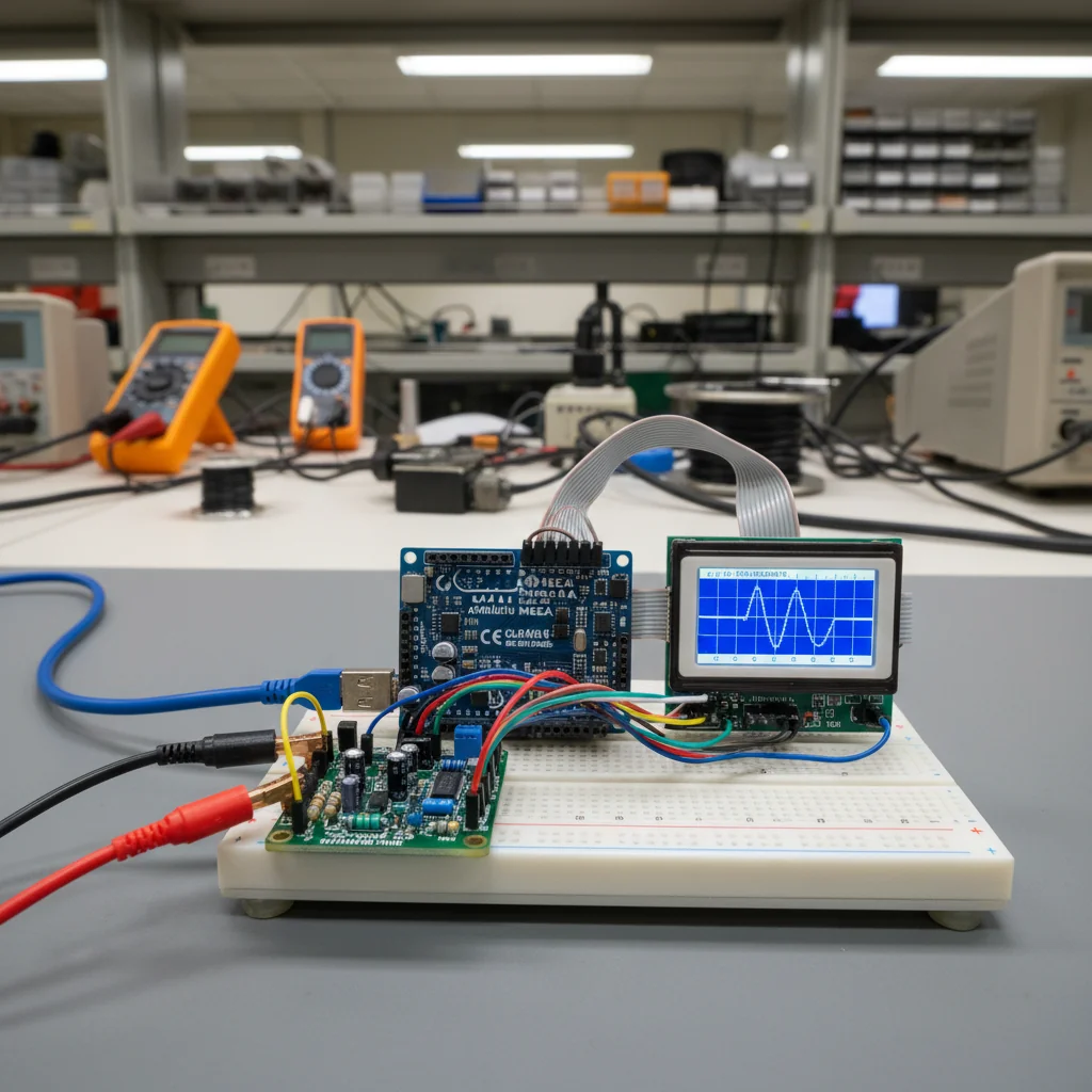
Arduino Based Oscilloscope
Build a low-cost Arduino-based oscilloscope to visualize analog signals, measure voltage and time variations, and understand signal behavior in real time.
Inclusive of all taxes
- Secure payments via Razorpay
- 7-day returns on defective items
- GST invoice on every order
Free delivery on orders above ₹2,000
Delivers in 4-7 business days
Check delivery at your pincode
₹3201.00
Inclusive of all taxes
Components
8 items
Difficulty
Advanced
Build Time
6 – 8 hours (hardware + firmware + visualization)
Project Details
How It Works
 How It Works
The Arduino samples analog signals at its A0 pin using the built-in ADC. The sampling rate is controlled by the code's delay between readings. Each analogRead() converts the voltage (0-5V) to a digital value (0-1023). These values are sent via Serial to a PC. The PC-side software (Serial Plotter, Processing, or Python with Matplotlib) receives these values and plots them as a waveform graph over time. Input protection circuits (resistor divider, Zener diode, capacitor) ensure the Arduino is not damaged by over-voltage or noise.
Prerequisites
Basic understanding of Arduino programming, analog signals, and electronics fundamentals. Familiarity with Arduino IDE and serial communication. Knowledge of voltage, current, and basic circuit concepts.
What You'll Learn
 What You'll Learn
Understanding how Analog-to-Digital Converters sample signals
Learning about signal sampling limitations and theory
Displaying waveforms on computer or display
Implementing circuits to protect and clean signals
Combining hardware sampling with software visualization
Understanding practical constraints of Arduino ADC
Key Features
Visualizes analog signals as they occur
Educational tool at minimal expense
Can be modified for different signal frequencies
Small form factor for easy use
Teaches core electronics concepts
Can be modified for multiple signal inputs
What's Included in the Kit
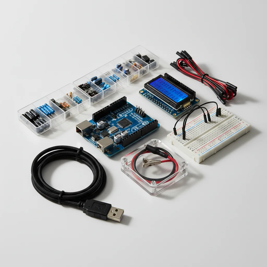
| Component | Qty | Price |
|---|---|---|
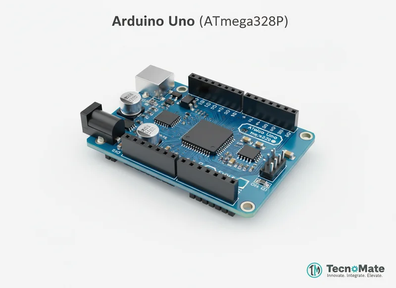 | 1 | ₹683.00 |
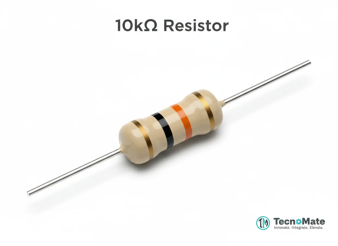 | 2 | ₹0.00₹0.00 × 2 |
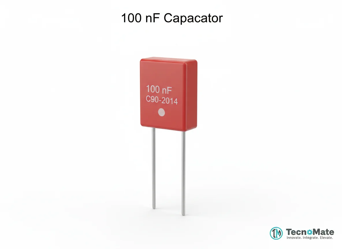 | 1 | ₹0.00 |
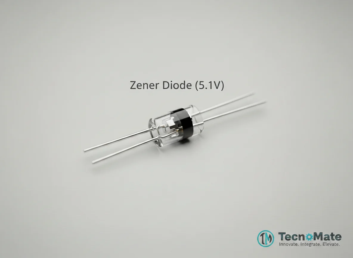 | 1 | ₹2.00 |
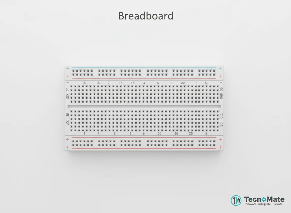 | 1 | ₹0.00 |
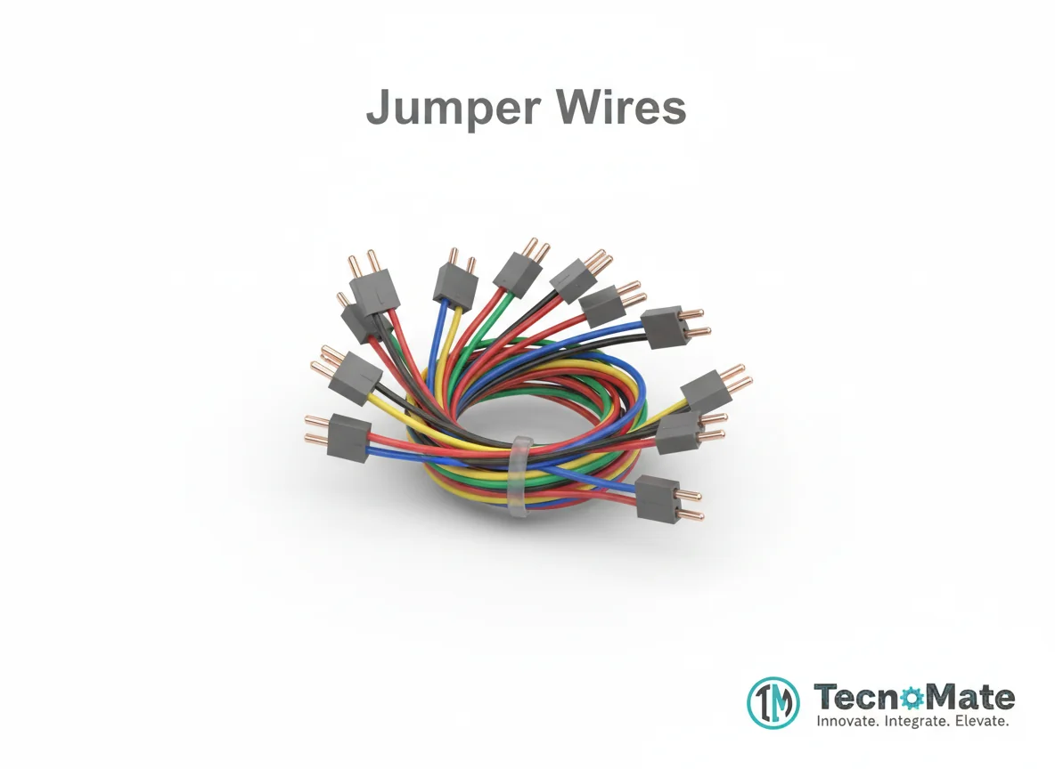 | 10 | ₹1523.00₹152.00 × 10 |
 | 1 | ₹169.00 |
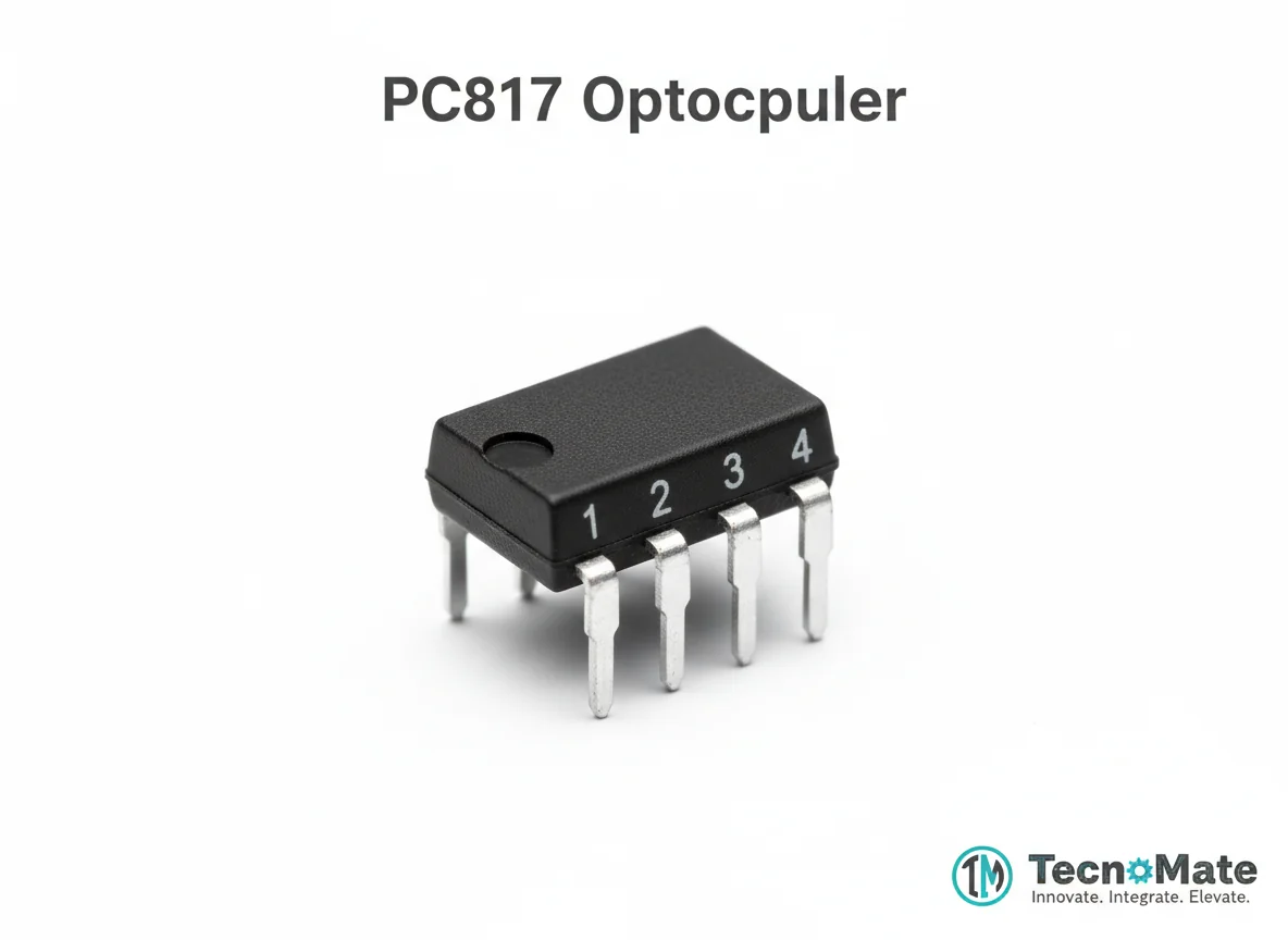 | 1 | ₹0.00 |
Operating Instructions
Pin Connections
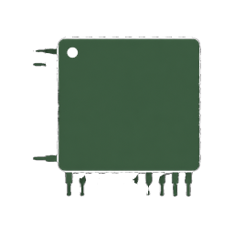 Pin Connections
| MCU Pin | Connected To | Purpose | Notes |
|---|---|---|---|
| A0 | Signal Input (via resistor divider) | Analog signal sampling | Input voltage must be 0-5V |
| GND | Signal Ground | Common ground reference | Required for proper signal measurement |
| N/A | Resistor Divider (10kΩ, 100kΩ) | Voltage limiting and protection | Limits input to 0-5V range |
| N/A | Zener Diode (5.1V) | Over-voltage protection | Clamps voltage above 5.1V |
| N/A | Capacitor (0.1µF) | Noise suppression | Filters high-frequency noise |
Tools Required
 Tools Required
Safety Precautions
Electrical
- ⚠Never apply voltage >5V directly to Arduino pins
- ⚠Always use resistor divider for input protection
- ⚠Do NOT connect AC mains directly to the circuit
Handling
- ⚠Verify signal source before testing
- ⚠Ensure common ground is properly connected
Operating
- ⚠This is for learning purposes only, not for professional measurements
- ⚠Maximum measurable frequency is ~5-10 kHz with Arduino Uno
Frequently Asked Questions
 Frequently Asked Questions
Q:Can this replace a real oscilloscope?
Q:What is the maximum frequency measurable?
Q:Can I make it dual-channel?
Q:Can I add LCD display?
Product images are for illustration purposes only. Actual products may differ in appearance, packaging, or specifications. See our Terms of Service.